 12-19-2011, 04:38 PM
|
#21 (permalink)
|
|
Master EcoModder
Join Date: Sep 2009
Location: Ireland
Posts: 734
Thanks: 26
Thanked 304 Times in 171 Posts
|
Adam , what load are you running on the controller?
__________________
Now, Cole, when you shift the gear and that little needle on the ammeter goes into the red and reads 2000 Amps, that's bad.
www.evbmw.com
|
|
|

|
 Today Today
|
|
|
|
 Other popular topics in this forum...
|
|
|
|
|
12-19-2011, 04:51 PM
|
#22 (permalink)
|
|
Master EcoModder
Join Date: Apr 2009
Location: Charlton MA, USA
Posts: 463
Thanks: 31
Thanked 183 Times in 94 Posts
|
Quote:
Originally Posted by dave koller

I have used ferrite beads with Bots to quench the ring - that help?
|
Where would the ferrite bead be placed? I have taken great care at making the gate and return traces perfectly overlapped. Ate on top and return on the bott of the board.
Damien, the load is a 12v starter motor and te supply is a 13.8v 10A wall supply that's isolated. The ring doesn't change from about 8% to 100% throttle.
-Adam |
|
|
|
|
12-19-2011, 05:14 PM
|
#23 (permalink)
|
|
EcoModding Apprentice
Join Date: Feb 2010
Location: Northern Wisconsin
Posts: 137
Thanks: 32
Thanked 39 Times in 23 Posts
|
That IS what the gate resistor is for, to slow the electrons down and force them to leave the gate in an orderly fashion. You can also aid this problem by putting a ferrite bead on the driver leg of the gate. I use it on mosfets but it is true for all drivers. Experiment ....
__________________
Dave  ...
|
|
|
|
|
12-21-2011, 08:18 AM
|
#24 (permalink)
|
|
Master EcoModder
Join Date: Apr 2009
Location: Charlton MA, USA
Posts: 463
Thanks: 31
Thanked 183 Times in 94 Posts
|
ALRIGHT!
Last night I was able to finish tuning the driver board. I did have some good scope shots, but my computer crashed when I tried to open them and they got currupt.... 
Yesterday I showed you this shot:
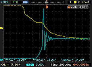 NewFile17
 by AdamBrunette, on Flickr
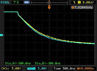
There is about 35V P-P. Well even though I lost my best capture, I have this one thats very close.
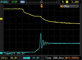 NewFile23
 by AdamBrunette, on Flickr
The scale is a little different, but you can see its getting better. The one I lost was showing about 22 or 24v P-P. I will get a new shot tonight. It also has very little ringing now. This is were I will leave it.
I ended up adding a diode to the turn on resistor and re-installed the turn off one. I am now running a 3.3R wire wound turn on, while not the ideal type, the inductance of the wire really helped without adding any other parts. The turn off is 2 carbon composition resistors 16R in value. In this pair, they create a resistor that is 8.45R. The carbon composition resistors tolerance sucks.... You cannot find 2 that are the same. While when I measure the 3.3R wire wound one, the 3 I picked are identical.
I was also able to measure some delays. From the driver to the gates everything is in the range of delay of 12nS max. And from one gate to the next, they are all in sync better then my scope can measure. Somewhere around < 3nS. Im pretty happy with this.
Here are the shots of rise from driver module to a gate.
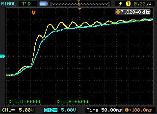 NewFile25
 by AdamBrunette, on Flickr
 NewFile26
 by AdamBrunette, on Flickr
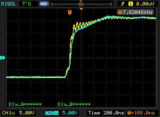
And delays between modules.
Rise:
 NewFile27
 by AdamBrunette, on Flickr
Fall:
 NewFile28
 by AdamBrunette, on Flickr
I will be doing high power and voltage tests starting tonight.
-Adam |
|
|
|
|
01-22-2012, 12:57 PM
|
#25 (permalink)
|
|
EcoModding Lurker
Join Date: Oct 2011
Location: Chandler, AZ
Posts: 23
Thanks: 9
Thanked 10 Times in 7 Posts
|
Adam;
Any new updates that you can share?
30 days since your last post.
Curiosity is getting the best of me. giggle-giggle
R J
|
|
|
|
|
01-23-2012, 03:49 PM
|
#26 (permalink)
|
|
Master EcoModder
Join Date: Apr 2009
Location: Charlton MA, USA
Posts: 463
Thanks: 31
Thanked 183 Times in 94 Posts
|
Quote:
Originally Posted by rayjay
Adam;
Any new updates that you can share?
30 days since your last post.
Curiosity is getting the best of me. giggle-giggle
R J
|
Hey RJ,
Ive been busy.
I have been testing and modifying the logic board for the controller, as well as working on my corvette and working on the 1000A controller. Its all coming together. I plan to try and test the controller tonight with the Uprising logic board on a hydraulic pump at 24V. This setup is capable of 110A for 10 minutes.
As for my car, The frame is finally done and now, I just have to strip the body and do the body work. My goal is the middle of april to be ready for the EV-ent down in Macungie PA on May 5th.
-Adam |
|
|
|
|
01-27-2012, 05:53 PM
|
#27 (permalink)
|
|
EcoModding Lurker
Join Date: Mar 2011
Location: Nashville
Posts: 17
Thanks: 9
Thanked 0 Times in 0 Posts
|
Update?
Any update on your progress? Great job!!
Quote:
Originally Posted by adamj12b
HAHA Im glad people are interested.
I have hit a little bit of a road block financially. I have to wait till my birthday rolls around in a couple weeks to order the last parts for the logic board. I still needed dc-dc converts, one of which will take some extra time to get because its special order. I also forgot the optos for the inputs so i cant test those yet.
Ive been working on wiring up a test stand for it and adding wires to the connector.
On monday the driver boards will be here. I was graciously donated the money to build them and plan to get that tested right away. I was hoping I could use the uprising board to do the testing of the driver board, but im going to have to use the old revolt board for pwm signal.
In other news, Ive got most of the 1kA controller built! The water plate is done and the cap and modules are mounted. All I got left is bus bars and install some new washers that came yesterday.
Here are some pics of the controller.
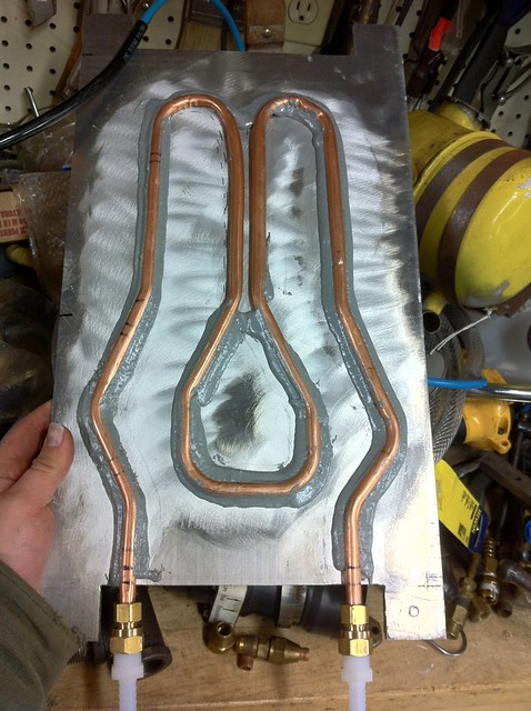 Untitled
 by AdamBrunette, on Flickr
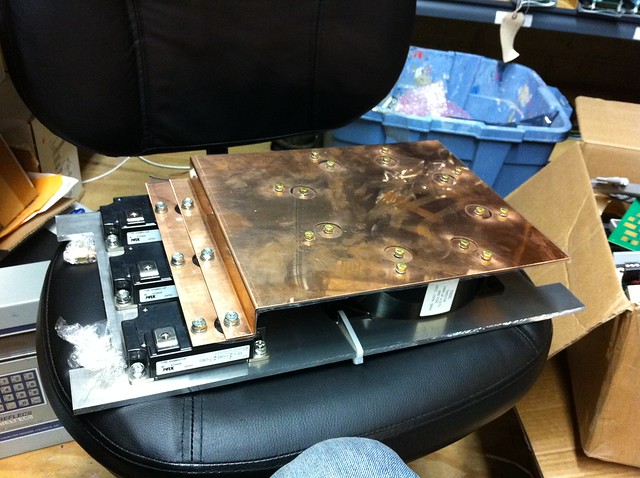 IMG_1285
 by AdamBrunette, on Flickr
-Adam |
__________________
Ferrari FXX EVO vs Prius
Ehh...nevermind.........
: )
|
|
|
|
|
03-20-2012, 08:47 AM
|
#28 (permalink)
|
|
Master EcoModder
Join Date: Apr 2009
Location: Charlton MA, USA
Posts: 463
Thanks: 31
Thanked 183 Times in 94 Posts
|
Well its been too long since an update, and im sorry.
I never stop working on things and its hard to find time to update my threads.
Well a good amount of work has happened since the last update.
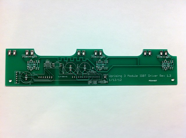
I have updated the driver board and I believe it is ready for production now. Mostly small changes that make it easier to mount and work on the IGBT modules. I have notched the edge of the board that is along the IGBT's so the mounting bolts can be removed now. I have also added diodes to the turn off section of the gate lead. This way, you can have 2 different resistors, one for turn on and one for turn off. I also added holes for 3 parallel gate resistors on the on side and 2 parallel on the off side. My plan is to use carbon composition resistors because they hold their resistance very well, but need to be manually paired to create the value needed. Im using 2 - 16R ones for about 8.3R for turn off and will be trying 3 parallel 10's for 3.33R for turn on. On the previous board, which is running happily in Isaac's snowmachine, is using a 3.1R wire wound resistor. The extra inductance helped a bit with waveform, but I plan to revisit this.
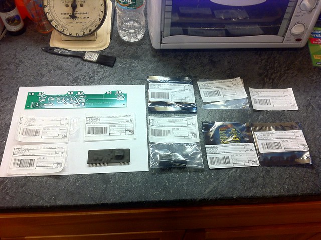
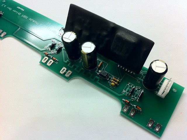
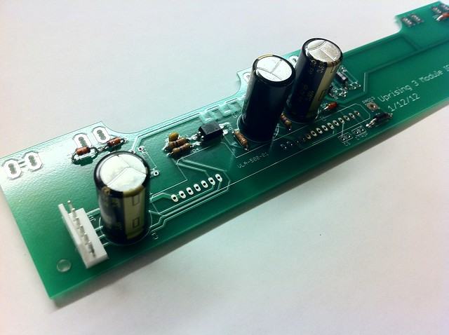
Here are some shots of the New driver board.
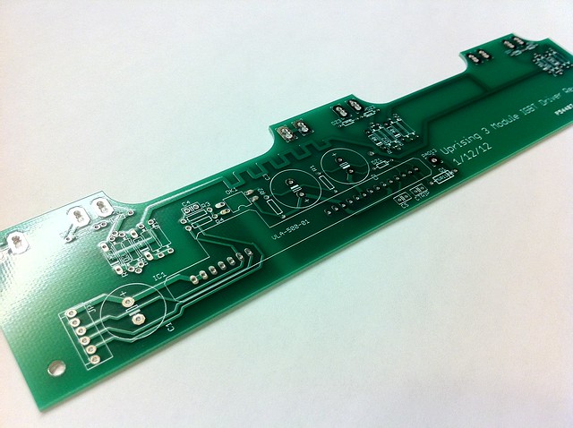 Untitled
 by AdamBrunette, on Flickr
 Untitled
 by AdamBrunette, on Flickr
 Untitled
 by AdamBrunette, on Flickr
 Untitled
 by AdamBrunette, on Flickr
 Untitled
 by AdamBrunette, on Flickr
 Untitled
 by AdamBrunette, on Flickr
As for the Uprising control board:
Eric and I have been working on the software for the controller. Lots of testing and bringing all the pieces together. We hit a roadblock when the original ATmega644p didn't have enough data memory (4k) and couldn't fit the new web interface information. We were trying to fill it 253% full!! We then upgraded the chip to a Atmega1284P which has 4x as much data space. It was a simple upgrade, just had to use some hot air to remove the old chip and some flux to mount the new chip. That took care of the hardware. Then we recompiled the code for the new processor and tried it out. It didnt work....  The status LED is now blinking much faster then it was with the original processor, and I cannot figure out why. Im still working at it though. My plan is to go back to the simple test programs that test each hardware section of the board and see if everything is working properly.
Well I think that's it for now. If anybody has ideas of what happened with the control board, I would love to hear them. Maybe I accidentally cooked it with too much hot air? I doubt it though...
-Adam
P.S. Here is the new picture of the control board!
 Untitled
 by AdamBrunette, on Flickr
Last edited by adamj12b; 03-20-2012 at 08:48 AM..
Reason: Added Picture
|
|
|
|
|
The Following 3 Users Say Thank You to adamj12b For This Useful Post:
|
|
|
03-20-2012, 02:01 PM
|
#29 (permalink)
|
|
Master EcoModder
Join Date: Sep 2009
Location: Ireland
Posts: 734
Thanks: 26
Thanked 304 Times in 171 Posts
|
Adam , your worse than AC propulsion You tease us with these wonderful products. I want one! ....... actually 2
__________________
Now, Cole, when you shift the gear and that little needle on the ammeter goes into the red and reads 2000 Amps, that's bad.
www.evbmw.com
|
|
|
|
|
03-20-2012, 02:14 PM
|
#30 (permalink)
|
|
ReVolt Enthusiast
Join Date: Jun 2009
Location: Michigan, USA
Posts: 239
Thanks: 98
Thanked 47 Times in 40 Posts
|
Quote:
Originally Posted by adamj12b
If anybody has ideas of what happened with the control board, I would love to hear them. Maybe I accidentally cooked it with too much hot air? I doubt it though ...
|
Hi Adam,
Thanks for all your hard work !!!
I don't have an answer for you about that microchip, debugging electronics can drive you crazy! You might have a solder bridge under the chip, you could try to do a quick toaster oven reflow of the whole PCB assembly. Flux around the chip and heatup the PCB, that would melt any small solder bridges. Just a long shot, might work?
A breakout board for the surface mounted micro would have make your life easier too ???
-Mark
|
|
|
|
|


