08-24-2011, 11:33 AM
|
#201 (permalink)
|
|
CFECO
Join Date: May 2008
Location: Vail, AZ.
Posts: 552
Thanks: 174
Thanked 60 Times in 56 Posts
|
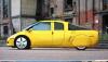
I have been pondering the same thoughts as in #199 when looking at the GM EV-1. The rear glass slopes much faster than the "Template" looking from the side, but it tapers in also when looking from above. One would guess the air which "follows around" from the side, helps "fill-in" what air may try to separate while coming over the top.
With the flat sides on a pick-up bed, and the cap tapers in at the rear, I would think the air around the cap would "want" the air along the side to come up and join it. When the bed edge is square that air cannot make a smooth flow up to the cap area, which probably causes the vortices and the less than ideal gains from the tapered cap.
|
|
|

|
|
The Following User Says Thank You to CFECO For This Useful Post:
|
|
 Today Today
|
|
|
|
 Other popular topics in this forum...
|
|
|
|
|
08-24-2011, 02:41 PM
|
#202 (permalink)
|
|
Master EcoModder
Join Date: Oct 2008
Location: Mid-Atlantic
Posts: 491
Thanks: 170
Thanked 69 Times in 44 Posts
|
Quote:
Originally Posted by CFECO

I have been pondering the same thoughts as in #199 when looking at the GM EV-1. The rear glass slopes much faster than the "Template" looking from the side, but it tapers in also when looking from above.
|
Or GM may have simply stretched the numbers, which incidently have been recently revised upward to Cd=.21.
Phil has offered us an analysis of what he is seeing on the EV1 and I'm certainly looking forward to that. I personally don't see the car as .21 when compared to the Insight 1 at Cd=.25, but I could well be wrong. The EV1 certainly has a couple of advantages. |
|
|
|
|
08-24-2011, 04:40 PM
|
#203 (permalink)
|
|
MPGuino Supporter
Join Date: Oct 2010
Location: Hungary
Posts: 1,807
iNXS - '10 Opel Zafira 111 Anniversary Suzi - '02 Suzuki Swift GL
Thanks: 828
Thanked 708 Times in 456 Posts
|
Quote:
Originally Posted by CFECO
When the bed edge is square that air cannot make a smooth flow up to the cap area, which probably causes the vortices and the less than ideal gains from the tapered cap.
|
This would appear to be a common mistake that many (including me) have made, in failing to note that air on the sides needs to move in the same general direction as air coming over the top. At speed, my version 2 bedcap makes pretty large counterrotating vortices on either side of the tailgate, and I am certain it's due to the fact that the side air is more-or-less going in a straight line, while the air coming from the top is moving downward. This is a good recipe for fuel-economy-robbing vortex generation.
I saw evidence supporting this when I re-read the Naval Post-Grad school paper on the Dodge Ram bedcap. The author's bedcap sloped downward, but evened out at the end. From the data in his report, I calculated a gain of about 15% from his aerocap alone, which is better than the 10% I found with my aerocap.
I think it should be emphasized that, for the last foot or so of the vehicle in question, all of the surfaces should ideally match each other with regard to slant. If the sides taper in just a little at the end, then the top should also. If the sides do not taper in at all at the end, then the top should also not taper at all. Version 3 of my bedcap will incorporate this.
Last edited by t vago; 08-24-2011 at 04:58 PM..
Reason: Added bit about NPS Dodge Ram aerocap
|
|
|
|
|
08-24-2011, 06:27 PM
|
#204 (permalink)
|
|
Master EcoModder
Join Date: Jan 2008
Location: Sanger,Texas,U.S.A.
Posts: 15,883
Thanks: 23,957
Thanked 7,219 Times in 4,646 Posts
|
simple
Quote:
Originally Posted by rfdesigner
This is a fascinating thread but I've been reading it and thinking most of the way along...
hey!, they're missing something.
Now maybe someone's dismissed this point already and I've missed it, maybe not, but my point seems to be illustrated by several car designs which appear to have steeper tails but claim good drag numbers.
The curves discussed in this thread are typically derived from NACA wing sections, but we're not dealing with a wing. A wing is very long compared to any other dimension, so it can to all intents and purposes be analysed as a 2D structure, each front to back section taken anywhere from the root to the tip of the wing can be thought of as being indistinguishable from the section adjacent to it.
But a car is inherently a 3D structure, the air over the centre line is very different to the air directly over the driver... (the best aero cars taper not just top to bottom, but side to side)
If we take a small but finite section of wing, all the air molecules at it's top edge will need to get back to the very tip of the trailing edge as the wing passes.
However in the simplest 3D case, a tapered dowl, not all the molecules around the fattest section will need to get back to the trailing point, only one need do this, the rest can fill a small tube around this, repeat this for each layer of molecules and the vast majority will not have to rebound terribly far.... in effect the air needs to rebound less in the 3D case than in the 2D thus one would expect higher angles in the idealised curve for a 3D object
A: have I got this all wrong?
B: has someone else already pointed this out?
Clearly if one is generating a simple curved kammback with flat sides then the wing section approach makes sense, but what if we're using complex compound curves.. can we get better performance in a shorter space?
Derek
|
*road vehicle aerodynamics include flow conditions which violate the criteria for wing performance and we are warned not to use tabulated data for wings when used in ground-effect.
*with respect to the aft-body contour,top & sides,Kamm did an an analysis of 'straight-sided' boat-tailing which can be compared to the 'Template' type.
* without the plan taper,tumble home,and edge radii of the 'Template' a full bot-tail body yielded Cd 0.21.
* with the streamline body of revolution plan curvature,tumble home,and massive radii of the 'Template' the body delivers Cd 0.13.
* the compound curves are part of the 'secret' to really low drag,although simple curved panels which approximate the more complicated body can deliver really fine performance.
* the 2.1:1 streamline body of revolution shows the lowest Cd in free flight and would produce a car body of Cd 0.08,but according to Mair's exclusive boat-tail investigation,has too steep an aft-body curvature to support attached flow all the way.
* Hoerner said that in actual practice,a body of fineness ratio greater than 2.1 would be the optimum.
* Hucho shows 2.5:1 at same Cd as 2.1 and when analyzed for aft-body tangent angles,just squeaks by for Mair's 22-degree angle limit.I believe it to be the shortest body which cannot have separation in 3-D flow in ground effect.
Last edited by aerohead; 08-25-2011 at 05:30 PM..
Reason: spelling
|
|
|
|
|
08-24-2011, 09:08 PM
|
#205 (permalink)
|
|
Master EcoModder
Join Date: Oct 2008
Location: Mid-Atlantic
Posts: 491
Thanks: 170
Thanked 69 Times in 44 Posts
|
Quote:
Originally Posted by aerohead
* Hucho shows 2.5:1 at same Cd as 2.1 and when analyzed for aft-body tangent angles,just squeaks by for Mair's 22-degree angle limit.I believe it to be the shortest body which cannot have separation in 3-D flow in ground effect.
|
Phil, is this fineness ratio for the full body of rotation or the half body? Also, when we speak of length, is it the total car length or just the length from the car's highest point? |
|
|
|
|
08-25-2011, 05:50 PM
|
#206 (permalink)
|
|
Master EcoModder
Join Date: Jan 2008
Location: Sanger,Texas,U.S.A.
Posts: 15,883
Thanks: 23,957
Thanked 7,219 Times in 4,646 Posts
|
full/half
Quote:
Originally Posted by jimepting
Phil, is this fineness ratio for the full body of rotation or the half body? Also, when we speak of length, is it the total car length or just the length from the car's highest point?
|
Jim,the 2.5 is for the streamline body.
When it is brought down to the ground-plane and then half submerged into the Prandtl/Rumpler mirror-image it produces a car body with an effective fineness ratio of 5:1 which Hucho eludes to as the shape of drag minimum when comparing the 1981 ARVW and 1978 Mercedes-Benz C-111 III rekordwagen.
With respect to length,that will be the vehicles overall length,but Hucho wants us to be thinking about effective length.
The height of the vehicle is the only parameter a person needs to use the 'Template' and it's taken at the highest point on the roofline,when ballasted to at least the EPA test load ( 300-lbs ). |
|
|
|
|
The Following 2 Users Say Thank You to aerohead For This Useful Post:
|
|
|
08-27-2011, 02:20 PM
|
#207 (permalink)
|
|
Master EcoModder
Join Date: Jan 2008
Location: Sanger,Texas,U.S.A.
Posts: 15,883
Thanks: 23,957
Thanked 7,219 Times in 4,646 Posts
|
side view
Quote:
Originally Posted by Frank Lee
I think complications come from having a 2D template with only a side view trying to define an optimal 3D form.
Just about every vehicle on that template pic is very aerodynamically efficient, yet just about every vehicle has a backlight that is steeper than the template. I don't think they'd have the low Cds if they suffered separation at the top of the backlight.
And then there are those like the Rumpler and the Boxfish that are aero but don't conform to the template very well at all.
Still, I like the template because if one uses it they won't go way wrong.
|
Frank,I agree with you about the limited scope of a single image.
I'm on the way to a 5-view set of drawings although this Bonneville thing has pretty much consumed all available time.
I'm also compiling a set of 'Template' comparisons to help explain some of the comments I've made about specific vehicles.
Also,I'd like to do a dedicated thread on plan-views of cars.These images are few and far between.
If everybody can hang on for awhile I'll get some stuff going.
I have six tables with me, sitting,waiting for Al to shake free and scan.
I think these will help the members with some of the Cd issues.  |
|
|
|
|
09-07-2011, 12:21 PM
|
#208 (permalink)
|
|
Aero Deshi
Join Date: Jan 2010
Location: Vero Beach, FL
Posts: 1,065
Thanks: 430
Thanked 668 Times in 357 Posts
|
Put the template on this truck.

BUMP |
|
|
|
|
09-08-2011, 01:40 AM
|
#209 (permalink)
|
|
EcoModding Lurker
Join Date: Jul 2010
Location: South Africa
Posts: 85
Thanks: 9
Thanked 12 Times in 8 Posts
|
@ChazInMT - I think you can move the template forward a bit. The rear of the cab already has some taper to it, so why 'undo' it?
__________________

|
|
|
|
|
09-08-2011, 06:37 AM
|
#210 (permalink)
|
|
Aero Deshi
Join Date: Jan 2010
Location: Vero Beach, FL
Posts: 1,065
Thanks: 430
Thanked 668 Times in 357 Posts
|
SvdM. Good observation, but no.
I have the template applied exactly as it is intended. The "Rules" of application are:
Scale the template up or down, without changing its relative ratio, to match the height of the vehicle from the bottom of the tires to the highest point of the roof. Then align the templates bottom chord on the bottom of the tires.
Align the template, front to back, over the vehicle so that the highest point on the template matches the highest point on the roof.
As I see it, what this does is allows for the shape to be applied to vehicles of differing height. Since a taller vehicle is going to raise the air up higher when it passes through it, the air is going to need more time to get back down on the rear of it after the vehicle has past. The template self adjusts, adding length to the extra height by scaling it up.
When I aligned the template in this GMC, I did exactly that. I went back to confirm it, and if you take a straight edge, and lower it down on the top of the roof, it hits within inches of where I place the top of the template. If anything, the straight edge showed I could move the template further back.
When deciding where to put the template, the existing shape is not a consideration. Very often, and as is the case here, the vehicle shape drops below the top line of the template. Does this mean we should build the aero cap to match the line at that point just behind the C-Pillar and stick up a bit? No. We just want the front of the cap to stay flat/flatter long enough to meet the curve again, and then ideally match its shape.
The cap would then look like this.

Here's a link to a bigger version.
Larger Picture of Denali with Top Line & Cap
|
|
|
|
|