 06-09-2008, 11:31 AM
|
#1 (permalink)
|
|
Master EcoModder
Join Date: Feb 2008
Location: belgium
Posts: 663
Thanks: 14
Thanked 61 Times in 44 Posts
|
boxing in turbulence and compound dams
the gist of this post is
"can you box in turbulence, as an alternatice to a smooth fairing"
i initially came to this while reading a wikipedia article on a defuser.
it seems to sugest the real merit of defuses is to allow air to chance in speed and pressure (at the rear of a car) in a controlled way, rather then to become turbulent. the later struck me as important.
Most cars these days have bumpers wich extend below the lowest visual part of the car, such as the spare wheel well and the exhaust system.
for a long time i thought this was just to hide these ugly parts from view, and was only adding drag by trapping the air behind. but than it struck me this might also contain the turbulence and uneven flow caused by these parts and allow the remainder to the air to decelerate in a more controlled way, thus decreasing overall drag, a bit the same as an airdam in reverse, or the pickup tailgate test upside down(wich showes up is better then down). is this still makeing sence?
than i got thinking further that if this is correct than any part of a cars (under) body that ideally should be faired over, but can't for practical reasons, might benefit from "boxing in", being surounded with small dams, wich create an air cussion around the part over wich smooth(er) airflow can exist.
another example would be the use of dams in front of the wheels (as seen on production cars) in favour of the aerodynamicly superior full fairing, wich isn't practicly possible, but also might cause lift or instability in crosswinds (something autospeed suspected in their "test" of such fairings, and wich was the reason for them to abandone the idea despite fuelsaveings).
so what about a "compound dam" a series on dams of increasing size placed at a certain distance of eachother in front of the wheels, the contours of wich approach that of an "ideal fairing". each fairing would have a low pressure area behind it, wich might create downforce and sidewinds would be able to pass trough the fairing wich perhaps helps stabilty further. as each fairing could be set up to flew the whole unit is practically invunerable to curb impacts, wich make full fairings impossible.
is my reasoning sound or am i mixing things up?
__________________
aer·o·dy·nam·ics: the science of passing gass
*i can coast for miles and miles and miles*
|
|
|

|
 Today Today
|
|
|
|
 Other popular topics in this forum...
|
|
|
|
|
06-10-2008, 06:26 PM
|
#2 (permalink)
|
|
Master EcoModder
Join Date: Jan 2008
Location: Sanger,Texas,U.S.A.
Posts: 15,883
Thanks: 23,957
Thanked 7,219 Times in 4,646 Posts
|
boxing in turbulence
lunarhighway, your question is a good one.What wikipedia might have mentioned in their article about diffusers,is that they do not work if flow ahead of the diffuser is not smooth and well attached.That usually means a belly-pan.As a palliative to under-body turbulence,front air-dams and rocker-panel extensions structure flow outside the region containing undercarriage protruberances, which would tear and trip otherwise "clean" flow.The "dams" determine where the air can go and endeavor to get the air to just barely clear underbody projections and wheel areas,allowing it to pass in a straight line to the vehicle rear.With respect to the built-up,or multi-panel leading-edge tire fairings,in theory,there's no reason why they wouldn't provide some minor benefit.Their leading edges would require enough radius so as to allow flow separation,and each trailing panel would also require proper radius.Without a central spine,the panels would only work at zero-yaw angles,as in any crosswind condition, there would be no inter-connecting structure to contain the flow and prevent bleed-out.The panels would still be required to respect the same ground-clearance limitations of a unitary fairing.
__________________
Photobucket album: http://s1271.photobucket.com/albums/jj622/aerohead2/
|
|
|
|
|
06-10-2008, 07:42 PM
|
#3 (permalink)
|
|
Old Retired R&D Dude
Join Date: May 2008
Location: Woburn Mass USA
Posts: 702
Thanks: 10
Thanked 18 Times in 17 Posts
|
Boxing in or covering over what might be a diffuser??
I have a big open space on the left side of the rear bumper. You could stick a bread box in that hole!

I didn't think too much about it before I removed the mud flaps. (This is before the mud flat was deleted).
That large member in the center (with the holes) is where a trailer hitch would mount.
Before:

After:

You can see the backs of those yellow mounting plugs on the top photo..
Before the flap deletion, the path between the left rear wheel and the void was blocked somewhat.
Now, it's wide open. It seems like air coming off the wheel is going to drive right into the void..
When I first saw the 'after' view, I had a strong urge replace the flap with a mini-flap that didn't extend down below the bottom of the low pointy part of the rear bumper. (Just below the bottom clip-nut).
I'm thinking of 3 choices:
1. Add a small (short) coroplas block where the old flap was screwed in.
2. Do number 1 and add a coroplas cover over the void, decreasing it's depth.
3. Do nothing at all and let the air go where it wants to, since the Void is really a diffuser..?.
Thanks for any comments.
Rich
__________________
Cheers,
Rich
Current ride: 2014 RAV4 LE AWD (24 MPG)
Wife's Pizza Transporter

|
|
|
|
|
06-11-2008, 06:03 AM
|
#4 (permalink)
|
|
Master EcoModder
Join Date: Feb 2008
Location: belgium
Posts: 663
Thanks: 14
Thanked 61 Times in 44 Posts
|
Xringer
my car looks similar, and i've also wondered how to improve the area, but i'm also leaning towards the defuser theory. Maybe not even a defuser but rather a simple crude duct that leads the air that enters the wheelwell out under the car. however viewn from below it does looks pretty bad.
if i an correct in my assumption air passes trough the duct than building a clean duct in there that can deal with the same volume of air would be an improvement, you could fair over the big hole in the bottom and just leave an opening for the air to exit
aerohead
.Without a central spine,the panels would only work at zero-yaw angles,as in any crosswind condition, there would be no inter-connecting structure to contain the flow and prevent bleed-out.
wouldn't this actually be a benefit? as the fairings intention is to direct air that goes front to back around a projection, however when the airflow comes in at an angle the original ideal solid fairing will sudenly become an obstruction to the air and ads frontal (or rather side) area to the profile, however with separate dams depending on the angle there will be less to no aditional frontal area and airflow will pass trough the fairing.
Their leading edges would require enough radius so as to allow flow separation,and each trailing panel would also require proper radius
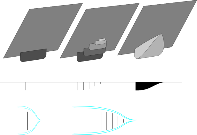
could you please explain what you mean be "enough radius"? i was thinking of a series flat dams like this
__________________
aer·o·dy·nam·ics: the science of passing gass
*i can coast for miles and miles and miles*
|
|
|
|
|
06-12-2008, 05:24 PM
|
#5 (permalink)
|
|
Master EcoModder
Join Date: Jan 2008
Location: Sanger,Texas,U.S.A.
Posts: 15,883
Thanks: 23,957
Thanked 7,219 Times in 4,646 Posts
|
Quote:
Originally Posted by lunarhighway

Xringer
my car looks similar, and i've also wondered how to improve the area, but i'm also leaning towards the defuser theory. Maybe not even a defuser but rather a simple crude duct that leads the air that enters the wheelwell out under the car. however viewn from below it does looks pretty bad.
if i an correct in my assumption air passes trough the duct than building a clean duct in there that can deal with the same volume of air would be an improvement, you could fair over the big hole in the bottom and just leave an opening for the air to exit
aerohead
.Without a central spine,the panels would only work at zero-yaw angles,as in any crosswind condition, there would be no inter-connecting structure to contain the flow and prevent bleed-out.
wouldn't this actually be a benefit? as the fairings intention is to direct air that goes front to back around a projection, however when the airflow comes in at an angle the original ideal solid fairing will sudenly become an obstruction to the air and ads frontal (or rather side) area to the profile, however with separate dams depending on the angle there will be less to no aditional frontal area and airflow will pass trough the fairing.
Their leading edges would require enough radius so as to allow flow separation,and each trailing panel would also require proper radius
could you please explain what you mean be "enough radius"? i was thinking of a series flat dams like this
|
The flat panels as depicted would have a drag coefficient of Cd 1.11 individually,although training behind one another,the second unit on back would be somewhat shielded in the wake of the very first panel.With Cd 1.11,the flow would immediately separate at the edges of the first panel,and it is doubtful that it would re-attach anywhere.That being the case,even though each successive panel is a bit larger,they would probably be embedded within the wake of the first panel.I apologize that I do not have the proper references with me,however,I believe that a radius that is 3-percent of the width of the panel is sufficient to prevent separation.Some side-view mirrors will have this minimum curvature at their edges.They don't look aerodynamically efficient,however,exhaustive research done for the VW Vanagon established the bare-minimums for leading-edge attached flow and I believe it to be good science.If the minimum criteria are met,then I believe the air will flow over the segmented fairing at zero-yaw,however,as the air begins to attack from the side,I believe it will travel transversely,colliding with the leeward free-stream,causing a turbulence more amplified than with a unitary fairing structure.I don't know.It's just how I perceive it.Any circulation of the air is vortex-drag which must be invested with engine power.The central spine might capture and arrest the transverse flow,pooling within the panel elements,allowing the free-stream to flow over it as though it were more a solid,fully skinned fairing.The Continuum Dynamic's 18-wheeler boat-tail functions on this principle,and will not allow the air to venture beyond where an ideal teardrop's trailing edge would let it go.Another thought is that with enough panels,the mass of the material used,begins to approach and possibly exceed the mass of a fully-contained fairing.Just a thought.
__________________
Photobucket album: http://s1271.photobucket.com/albums/jj622/aerohead2/
|
|
|
|
|


