10-06-2017, 12:04 AM
|
#11 (permalink)
|
|
Master EcoModder
Join Date: Feb 2010
Location: Elmira, NY
Posts: 1,782
Thanks: 319
Thanked 356 Times in 297 Posts
|
Sailplane cockpit exhaust system from South Africa is at top center behind the canopy.
|
|
|

|
|
The Following User Says Thank You to Grant-53 For This Useful Post:
|
|
 Today Today
|
|
|
|
 Other popular topics in this forum...
|
|
|
|
|
10-06-2017, 12:12 AM
|
#12 (permalink)
|
|
It's all about Diesel
Join Date: Oct 2012
Location: Porto Alegre, Rio Grande do Sul, Brazil
Posts: 12,562
Thanks: 0
Thanked 1,625 Times in 1,450 Posts
|
When there is any mention to "redneck A/C", the first thing that comes across my mind are those swamp-coolers widely used by truckers in my country. Anyway, maybe it would worth to perform some experiences with a Venturi tube and a small fan as some sort of "redneck A/C".
|
|
|
|
|
10-06-2017, 12:30 AM
|
#13 (permalink)
|
|
EcoModding Lurker
Join Date: Mar 2015
Location: Texas
Posts: 29
Thanks: 15
Thanked 11 Times in 11 Posts
|
Freebeard and anyone still here...
This is roughly what I'm trying to do (link)
https://1drv.ms/u/s!ApZC8QFk-svmgXNKbTVyLAgQpdaF
According to Flow Illustrator it
can work...what comes out of the wheel well follows the interior roof bottom line to the back and is released into the vacuum in the rear of the car. My question is if the inlet/outlet points for air in the interior or roof angle can be improved and how. |
|
|
|
|
The Following User Says Thank You to mikesheiman For This Useful Post:
|
|
|
10-06-2017, 02:01 AM
|
#14 (permalink)
|
|
Master EcoModder
Join Date: Aug 2012
Location: northwest of normal
Posts: 27,665
Thanks: 7,767
Thanked 8,575 Times in 7,061 Posts
|
Your CFD modeling of the interior is probably inadequate. CFD in general requires supercomputer levels of compute power. The modeling is not representative and the resolution is too coarse. Sorry.
You can click on your username, go to your profile and create an album to put you pictures in. then you can place them directly in the thread. You'll get more eyeballs on the problem.
You might CFD model the intake or exhaust port. Or you could observe best practices in the field. NACA ducts for intake, but they don't help on exhaust. Etc.
Were it I; the front wheelwells would follow this:
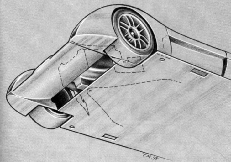
You already have a start with the open fender backs. Think about the relative volumes of the air swirling in the underbody, the amount needed for cabin ventilation and the amount needed for intercoolers on the apparently electric drivetrain.
Have you settled on a motor or would you like to hear an opinion on that?
If the exhaust vent is on the top of the canopy where high velocity air can pull it out, that could be a good location. You could probably have cabin air exhaust into the engine compartment. It may or may not require additional inlets. |
|
|
|
|
The Following User Says Thank You to freebeard For This Useful Post:
|
|
|
10-06-2017, 11:37 AM
|
#15 (permalink)
|
|
EcoModding Lurker
Join Date: Mar 2015
Location: Texas
Posts: 29
Thanks: 15
Thanked 11 Times in 11 Posts
|
Quote:
Originally Posted by freebeard

Your CFD modeling of the interior is probably inadequate. CFD in general requires supercomputer levels of compute power. The modeling is not representative and the resolution is too coarse. Sorry.
|
Hmm...well is there free modelling software around that can handle it?
I may not have a super computer, but do have an 8 core I7 I use for music and hobbiest scientific processing.
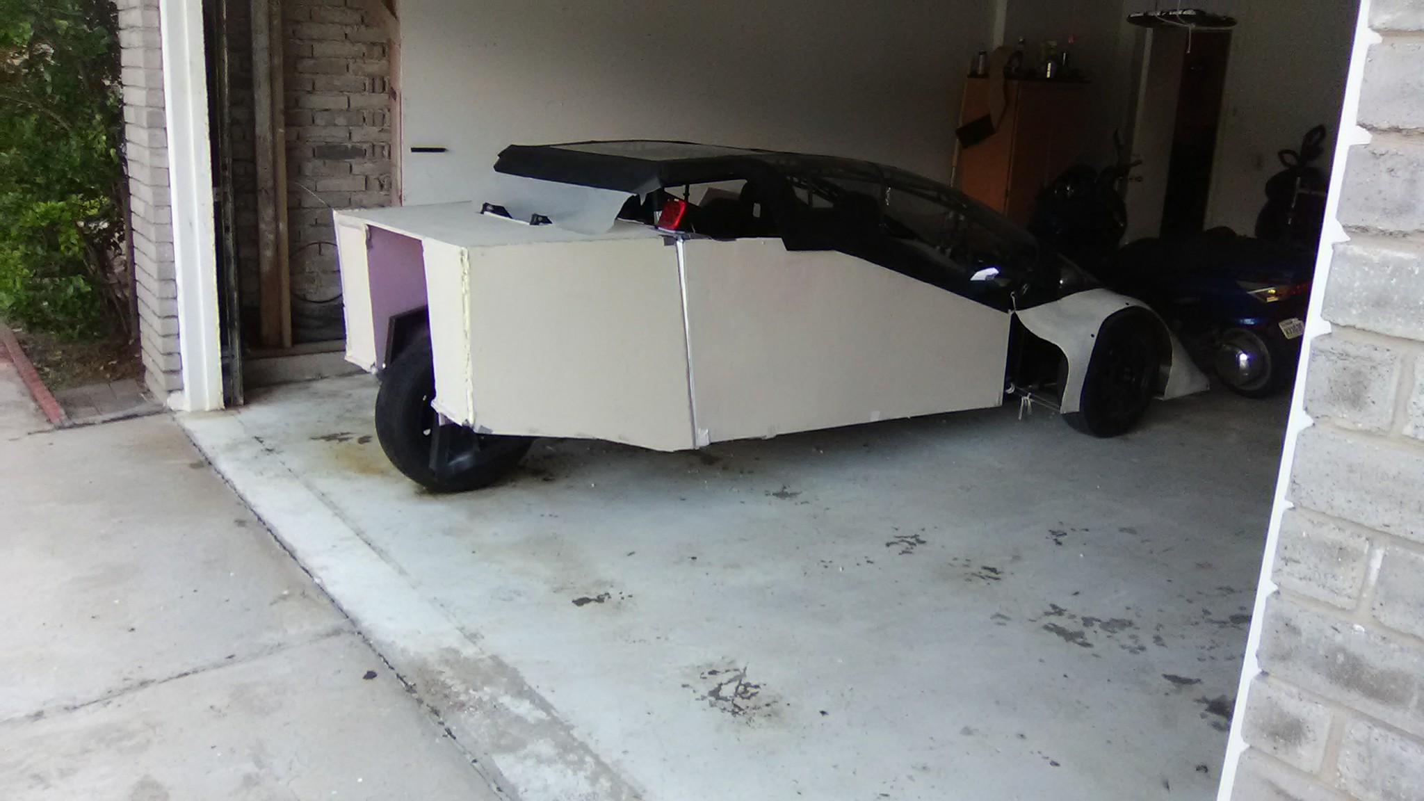
Here is another pic of the car/trike. Problem with my model vs. your suggestion I see is how to apply it to a car with open wheel wells in the back.
Quote:
Originally Posted by freebeard
You might CFD model the intake or exhaust port. Or you could observe best practices in the field. NACA ducts for intake, but they don't help on exhaust. Etc.
|
That's exactly it...I can't seem to find any best practices on cabin exhaust. It seems the top-center of the rear canopy may be a good exhaust point, but ditto for the bottom center right behind the plenum formed in the rear center where the rear wheel and (indeed electric) motor are.
My concern with exhausting it top center of the rear canopy is wouldn't that change/disrupt the flow of quick moving air at the top-rear of the car, causing the airflow from the bottom to circle back into a vacuum in the top rear area. Or, again, I'm wondering if that effect is not real, but just a problem with the Flow Illustrator wind tunnel simulator.
Would you recommend a top/center outlet over a bottom/center one? Or where on the photo, for example, would you recommend it?
Right now I'm using a Mars ME1003 motor, which delivers about 15-20 HP continuous without overheating at about 150-200 amps with 72v (using a high-end golf-cart motor controller, the Alltrax SR72550). People take telling me to get a bigger motor  , but my ideal goal is to make it haul 4 people to 60 mph using just that amount of power e.g. efficiently  . It may not be an eVLC (I wish I had the skills to fabricate that sort of avian shape), but the fact an eVLC did the job with a similarly powered motor gives me some hope.
I'll probably repost this with global/album pics...soon as I get some background learning from this thread so I don't test people's patience too much with my novice-ness.
|
|
|
|
|
10-06-2017, 01:45 PM
|
#16 (permalink)
|
|
Master EcoModder
Join Date: Aug 2012
Location: northwest of normal
Posts: 27,665
Thanks: 7,767
Thanked 8,575 Times in 7,061 Posts
|
Quote:
Originally Posted by mikesheiman
Hmm...well is there free modelling software around that can handle it?
I may not have a super computer, but do have an 8 core I7 I use for music and hobbiest scientific processing.
|
OpenVDB: An Open Source Data Structure and Toolkit for High-Resolution Volumes
When I went looking for the thread, I learned that no-one had commented on it. 
Quote:
That's exactly it...I can't seem to find any best practices on cabin exhaust. It seems the top-center of the rear canopy may be a good exhaust point, but ditto for the bottom center right behind the plenum formed in the rear center where the rear wheel and (indeed electric) motor are.
My concern with exhausting it top center of the rear canopy is wouldn't that change/disrupt the flow of quick moving air at the top-rear of the car, causing the airflow from the bottom to circle back into a vacuum in the top rear area. Or, again, I'm wondering if that effect is not real, but just a problem with the Flow Illustrator wind tunnel simulator.
Would you recommend a top/center outlet over a bottom/center one? Or where on the photo, for example, would you recommend it?
|
In clean, moving air not buffeting turbulence. But seek other opinions.
Quote:
|
Right now I'm using a Mars ME1003 motor, which delivers about 15-20 HP continuous without overheating at about 150-200 amps with 72v (using a high-end golf-cart motor controller, the Alltrax SR72550).
|
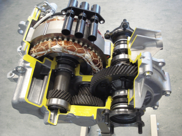
I have one of these. The Toyota engineering is indistinguishable from magic. There was some discussion of locking the differential for a motorcycle. 50hp/68NM.
Controller mods or build for E-assist altermotor
These are 20hp; which won't be sufficient uphill in a headwind.
|
|
|
|
|
10-07-2017, 01:42 PM
|
#17 (permalink)
|
|
Master EcoModder
Join Date: Jan 2008
Location: Sanger,Texas,U.S.A.
Posts: 15,883
Thanks: 23,957
Thanked 7,219 Times in 4,646 Posts
|
Reynolds number is problematic
Quote:
Originally Posted by mikesheiman
Freebeard and anyone still here...
This is roughly what I'm trying to do (link)
https://1drv.ms/u/s!ApZC8QFk-svmgXNKbTVyLAgQpdaF
According to Flow Illustrator it
can work...what comes out of the wheel well follows the interior roof bottom line to the back and is released into the vacuum in the rear of the car. My question is if the inlet/outlet points for air in the interior or roof angle can be improved and how. |
With a Rn of 5,000,this flow would be of a laminar boundary layer,not possible when the entire vehicle is submerged in the turbulent boundary layer of Earth.
And there's a risk that air would actually flow forwards,from the back of the car to the front,seeking fast-moving,low-pressure regions up front.
__________________
Photobucket album: http://s1271.photobucket.com/albums/jj622/aerohead2/
|
|
|
|
|
The Following User Says Thank You to aerohead For This Useful Post:
|
|
|
10-07-2017, 02:37 PM
|
#18 (permalink)
|
|
Master EcoModder
Join Date: Aug 2012
Location: northwest of normal
Posts: 27,665
Thanks: 7,767
Thanked 8,575 Times in 7,061 Posts
|
Quote:
Recommended rear shape and/or ducting
I have the following project trike (4-seater, like an extended Polaris Slingshot, with 3 wheels to make it street legal as a motorcycle) and am working on the tail end.
This image has been resized. Click this bar to view the full image. The original image is sized 2048x1152.
I made that admittedly amateur sheet foam tail myself, but am curious if I, say, should be using a more or less aggressive tapering angle and also curious what I should do for the (now open) top. Any ideas?
Will post more pics at different angles when I get home.
|
Since your other thread has zero response I'll respond here.
Putting side-by-side seating in the rear could potentially create bad vehicle dynamics. It also compromises plan taper. If you are committed to a four-seater, then — Oh, well. Else, a central rear seat, moved forward, with footroom under the elbows of those in front .
It's hard to comment without an indication of the [presumed] door cut-lines. The front fender cutouts seem low and wide, but it's hard to know without a better understanding of the cross-section through the front suspension.
You are trying to make a aerodynamic shape from flat sheets. They will fight you every step of the way. It may be better to make an eggcrate from foam strips and then carve the outer face of the eggcrate to shape.
At least make one continuous curve down the side without steps on the edges. That back-facing rectangle should be an oval. |
|
|
|
|
10-07-2017, 03:28 PM
|
#19 (permalink)
|
|
Master EcoModder
Join Date: Jan 2008
Location: Sanger,Texas,U.S.A.
Posts: 15,883
Thanks: 23,957
Thanked 7,219 Times in 4,646 Posts
|
behind the car
Quote:
Originally Posted by mikesheiman
Any clue how to improve this to increas
aerodynamics while ventilating the cabin?
I am curious if the rear roof angle is ideal and if there is an ideal hole placement/size in the back to empty air into the vacuum behind the car from the cabin.
Edit this is **not** for an existing model car, but for a prototype I have built from scratch (see pic, which I have repost outside of Facebook to ensure it is visible)
https://1drv.ms/i/s!ApZC8QFk-svmgXIZdrsgSxXP-kV8 |
Some thoughts:
*streamlining is to reduce pressure drag.
*Pressure drag is a function of separated flow.
*To reduce the pressure drag you need to attack flow separation.
*Behind the front wheels is a major source.The fenders can be extended into side pods,like Peraves used on their Monotracer,which will add streamlining and crush zone protection in the event of a side impact.
*Behind the notched roof.
*Behind the abruptly-chopped body rear.
*The sharp corners on the upper edges are a source of vorticity,also a source of drag.
*You'll be disappointed to know that it's a dead end,attempting to fill the turbulent wake by injecting cabin air.
*The solution is always to get the air around and to the rear of whatever you have without allowing the flow to be tripped into eddies and turbulence.Once the air is turbulent,there is absolutely no way to recover any of the kinetic energy of this swirling mass.The less air which passes through the body the better.
------------------------------------------------------------------------
As to cabin ventilation,you can run a ram-air tube from the forward stagnation area of the trike and duct this high pressure air into the cabin,or harvest fast-moving air with a NACA submerged inlet,ducting this converted,high pressure air in.
__________________
Photobucket album: http://s1271.photobucket.com/albums/jj622/aerohead2/
|
|
|
|
|
The Following 2 Users Say Thank You to aerohead For This Useful Post:
|
|
|
10-08-2017, 12:48 PM
|
#20 (permalink)
|
|
Master EcoModder
Join Date: Jun 2008
Location: Earth
Posts: 5,209
Thanks: 225
Thanked 811 Times in 594 Posts
|
Quote:
Originally Posted by freebeard
CFD in general requires supercomputer levels of compute power.
|
Which you might well be able to get from a midrange NVidia graphics card. You might want to check their site to see if anyone has done a CFD app.
|
|
|
|
|