 07-29-2015, 04:44 PM
|
#31 (permalink)
|
|
Master EcoModder
Join Date: Jan 2008
Location: Sanger,Texas,U.S.A.
Posts: 15,895
Thanks: 23,972
Thanked 7,223 Times in 4,650 Posts
|
bellmouth
Quote:
Originally Posted by Cycle

As regards the bellmouth opening that'll provide cooling air to the engine compartment (and ultimately air that'll fill the wake of the bike), I just wanted to archive this here:
AutoSpeed - Building and Testing an Airbox
"Bellmouths
The sharpness of the radius of the lip that surrounds a bellmouth is important. If it is too tight, the airflow ‘unsticks’ on the transition around the corner and the intake flow is reduced.
In Axial Flow Fans and Ducts (R. Alan Wallis, 1983, John Wiley and Sons, ISBN 0-471-87086-2) the minimum radius of the bellmouth lip is specified as being best between 0.25 and 0.3 times the diameter of the tube. So for example, a 7.5cm tube should have a bellmouth that has a radius of curvature that is 1.9 – 2.3cm. (Where did these figures come from? 7.5 x 0.25 = 1.9, and 7.5 x 0.3 = 2.3).
To turn it into data that can be more readily used, the diameter of a disc that can be nestled inside the outer face of the bellmouth lip should be 0.5 – 0.6 times the diameter of the tube. Most bellmouths are in fact smaller than this – these represent figures to be strived for."
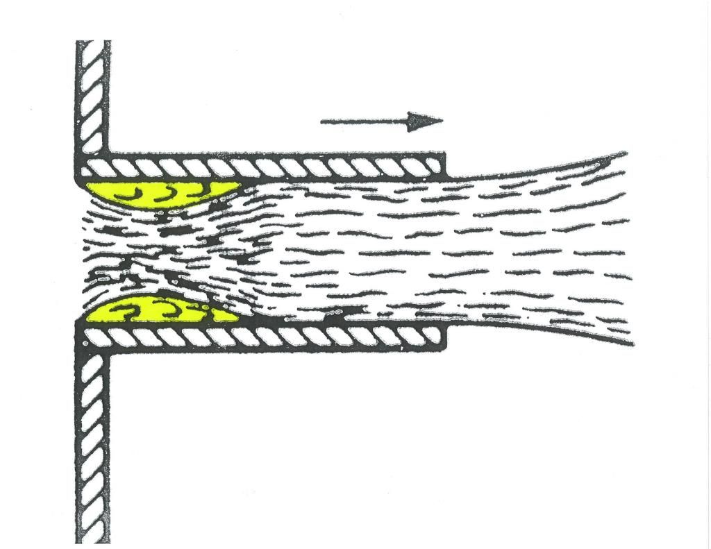
So the curve of the bellmouth should be 0.5 to 0.6 times the inner diameter of the tube the bellmouth is feeding, to prevent air from detaching as it enters the bellmouth. |
In this Borda Tube you can see what happens without a bellmouth.The yellow areas are the choking vena contractas which essentially limit the flow volume.
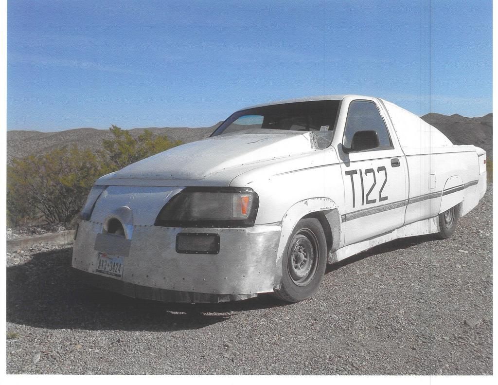
Jet turbine inlets are optimized for inlet efficiency,as well as at least one trashcan lid.Half the 'lid' was plenty for 1-mile W.O.T. passes at Bonneville.
If you look around,there are also cake molds and Jello molds which might help on the bike project.
__________________
Photobucket album: http://s1271.photobucket.com/albums/jj622/aerohead2/
Last edited by aerohead; 07-31-2015 at 05:10 PM..
Reason: spelling
|
|
|

|
 Today Today
|
|
|
|
 Other popular topics in this forum...
|
|
|
|
|
07-29-2015, 07:08 PM
|
#32 (permalink)
|
|
EcoModding Lurker
Join Date: Mar 2015
Location: California
Posts: 92
Thanks: 10
Thanked 19 Times in 17 Posts
|
Ok, next question... what software is there that will let a fatally artistically challenged (but extremely mechanically and analytically-inclined) person virtually construct a trellis-frame bike and test it for load and flex? Preferably free. Could CalcuLix do this?
I'll be using 4130 chrome-moly seamless tube with gusseting to reinforce the joints. The floorpan (where your feet rest) will be aluminum honeycomb sandwich panel (1/2" thick, only 1.2 pounds per square foot and able to hold 330 pounds of weight). The primary goal is a strong flex-free frame that is as light as possible to improve power:weight ratio.
My front suspension setup will be similar to the Bob Horn setup, with a similar non-steering setup in back. That'll let me adjust alignment, rake and trail, and gives a very low front end (especially with only a 13" front tire). The steering linkage will be dual pre-tensioned linkages so there's no steering slop.
To be 50-state legal (just in case I want to ride in other states), minimum seat height has to be 26" and minimum headlight height has to be 24", which leaves plenty of room around the front wheel for the ducting. I plan on having aerodynamic cutouts plenty large enough that I can get my feet out to balance at stops. They'll be designed to scoop some of the underbody air (the underbody will have two half-ducts that channel the air to the openings) and inject it into the passenger space to push the turbulent air up and over the rider. It'll be faired on the sides (with a small door to make entry easier), and the rider will sit inside the frame, for better crash protection. The body will be fully enclosed at the front (including the wheel), extend up to shoulder height in the rider space, then mimic the outline of the rider behind the rider space, tapering to a thin Kamm tail with the engine-exhaust-driven Coanda nozzle to inject engine exhaust and engine compartment warm air into the wake.
I'm going to attempt to use OpenFoam to model the aerodynamics, but like I said, I have zero artistic ability... so I'll likely get frustrated and hire it done.
This bike is pig-heavy for such a small one... curb weight of 338.8 pounds, although I've removed the rear seatrest / luggage rack which was 8.4 pounds (2.48% of the total weight!). Lots of components on this bike are heavier than they need to be... the metal plate that fits over the gas tank and reinforces the floor where your feet go weighs just over 6 pounds alone. It adds no structural strength to the frame, it's just there for your feet. I think I'll be able to find a lot of weight savings in getting rid of the heavy steel frame and all the heavy metal they've hung on this bike.
|
|
|
|
|
07-29-2015, 09:52 PM
|
#33 (permalink)
|
|
EcoModding Lurker
Join Date: Mar 2015
Location: California
Posts: 92
Thanks: 10
Thanked 19 Times in 17 Posts
|
I did the calculations for effective wind speed and angle, and put them in a spreadsheet.
It's titled "Wind Speed and Angle.ods". It's in OpenOffice.org .ODS format. See the attached file, zipped up.
I assumed the worst-case scenario of the wind hitting the bike at a 90 degree angle to its direction of travel. I calculated for wind speeds from 0 to 75 MPH, and bike speed from 0 to 150 MPH. You'll note the effective wind speed is always greater than the forward speed of the bike, and much greater than the actual wind speed... so the cross-ducting should work pretty well.
For instance, at 65 MPH forward speed and 25 MPH wind speed at a 90 degree angle, the effective wind speed is 69.642 MPH at 21.038 degrees. A 25 degree scoop would get pretty much the full blast of that effective wind speed, delivering a blast of air to the other side of the bike that exceeds the actual wind speed by ~44 MPH. That would push on the other side of the bike pretty effectively to counteract the side wind.
As the forward speed of the bike increases, the effective wind speed hitting the bike increases, and the angle at which it's hitting the bike decreases. So if I make the inlets at a 25 degree angle, that'll account for quite a variation in wind speed.
The natural inclination when getting hit with a side wind is to slow down. But that may not be the best choice with a cross-duct system... as you slow down, the effective wind speed drops, but the angle increases rapidly. You want to be traveling at a faster speed than the speed of the side wind. I'll have to figure out how to create some electronics that measures side wind and forward speed and recommends the best speed.
Last edited by Cycle; 07-29-2015 at 10:21 PM..
|
|
|
|
|
07-30-2015, 03:25 PM
|
#34 (permalink)
|
|
EcoModding Lurker
Join Date: Mar 2015
Location: California
Posts: 92
Thanks: 10
Thanked 19 Times in 17 Posts
|
Quote:
Originally Posted by Cycle
Ok, next question... what software is there that will let a fatally artistically challenged (but extremely mechanically and analytically-inclined) person virtually construct a trellis-frame bike and test it for load and flex?
|
Found some software:
Bend-Tech Super SE Tube Bending Software
Has anyone ever used this? How hard is it to use? |
|
|
|
|
07-30-2015, 04:14 PM
|
#35 (permalink)
|
|
Master EcoModder
Join Date: Aug 2012
Location: northwest of normal
Posts: 27,696
Thanks: 7,775
Thanked 8,585 Times in 7,069 Posts
|
What did you think of Designing Tubular Frame Structures in Building Ultra Light-Weight Tubular Frame Vehicles, Part 1. That blew my mind the first time I read it. It seems to me if you use drawn wire (stretched enough that it's perfectly straight) and use pre-measured dollops of solder; then you could get a reproducible and therefore useful result.
About the software: All I see is $599, running on Windows, used to drive an industrial tubing bender. What's you OS and price point? Beyond ease of use, does it even do what you want? Which is probably Finite Element Analysis....with some detailingI liked Working With Tubular Frames for that.
Also, what was the topic for this thread again? |
|
|
|
|
07-31-2015, 10:51 AM
|
#36 (permalink)
|
|
EcoModding Lurker
Join Date: Mar 2015
Location: California
Posts: 92
Thanks: 10
Thanked 19 Times in 17 Posts
|
Quote:
Originally Posted by freebeard
Also, what was the topic for this thread again?
|
Haha! Yeah, topic drift. But at least it's tangentially related to the original topic... to experiment with electroaerodynamic drag reduction, I have to have a body, to have a body, I need a frame to mount it to, to build the frame I need tubing, to measure and fit the tubing, as well as determine frame flex rate and load bearing capacity, I need tube fitting software... it'll all come together eventually. We're at the "bulge in the belly" of the snake after it's swallowed a large meal. I just hope the end product doesn't look like what comes out the other end of the snake. :) |
|
|
|
|
07-31-2015, 01:14 PM
|
#37 (permalink)
|
|
Master EcoModder
Join Date: Aug 2012
Location: northwest of normal
Posts: 27,696
Thanks: 7,775
Thanked 8,585 Times in 7,069 Posts
|
|
|
|
|
|
The Following User Says Thank You to freebeard For This Useful Post:
|
|
|
07-31-2015, 05:33 PM
|
#38 (permalink)
|
|
Master EcoModder
Join Date: Jan 2008
Location: Sanger,Texas,U.S.A.
Posts: 15,895
Thanks: 23,972
Thanked 7,223 Times in 4,650 Posts
|
counteract
Quote:
Originally Posted by Cycle
I did the calculations for effective wind speed and angle, and put them in a spreadsheet.
It's titled "Wind Speed and Angle.ods". It's in OpenOffice.org .ODS format. See the attached file, zipped up.
I assumed the worst-case scenario of the wind hitting the bike at a 90 degree angle to its direction of travel. I calculated for wind speeds from 0 to 75 MPH, and bike speed from 0 to 150 MPH. You'll note the effective wind speed is always greater than the forward speed of the bike, and much greater than the actual wind speed... so the cross-ducting should work pretty well.
For instance, at 65 MPH forward speed and 25 MPH wind speed at a 90 degree angle, the effective wind speed is 69.642 MPH at 21.038 degrees. A 25 degree scoop would get pretty much the full blast of that effective wind speed, delivering a blast of air to the other side of the bike that exceeds the actual wind speed by ~44 MPH. That would push on the other side of the bike pretty effectively to counteract the side wind.
As the forward speed of the bike increases, the effective wind speed hitting the bike increases, and the angle at which it's hitting the bike decreases. So if I make the inlets at a 25 degree angle, that'll account for quite a variation in wind speed.
The natural inclination when getting hit with a side wind is to slow down. But that may not be the best choice with a cross-duct system... as you slow down, the effective wind speed drops, but the angle increases rapidly. You want to be traveling at a faster speed than the speed of the side wind. I'll have to figure out how to create some electronics that measures side wind and forward speed and recommends the best speed.
|
The volume of air leaving the duct would be miniscule compared to the volume of the leeward separated wake of the rig.I can't imagine that the duct provides enough porosity in the body to compensate for the pressure differential across the body.
Consider the central blow hole in a conventional military parachute canopy.Yes the chute is ventilated,but it still has Cd 1.35.If you land in a wind you must cutaway the capewells or the thing will drag you to your death even though it's 'ducted.'
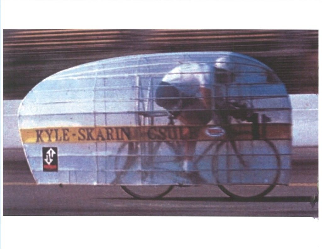
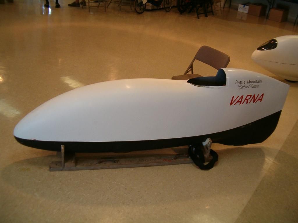
I'd have to check,but I think that competition at Battle Mountain is suspended if cross-course winds exceed 8-mph.These bikes just blow over and skid into the desert brush.
__________________
Photobucket album: http://s1271.photobucket.com/albums/jj622/aerohead2/
Last edited by aerohead; 07-31-2015 at 05:38 PM..
Reason: add info
|
|
|
|
|
07-31-2015, 05:50 PM
|
#39 (permalink)
|
|
EcoModding Lurker
Join Date: Mar 2015
Location: California
Posts: 92
Thanks: 10
Thanked 19 Times in 17 Posts
|
I've been considering an alternative... a lengthwise "slit" or "slits" along the bottom length of the bike, with a "step" to it (them), so that as you lean into a side-wind, it opens that "slit" (slits) up to the cross-wind. It'd duct the air through the underbelly to the other side of the bike, to an identical "slit" (slits), pushing that air to the leeward lower-pressure side of the bike.

That'd provide a huge amount of porosity while not creating any drag in straight-line riding. Of course, that means the forward speed of the bike isn't used to ram air into the duct, capitalizing on the forward speed to contribute to side-wind cancellation.
Perhaps a combination of the two... ram air ducts feeding the horizontal slits. A side wind would force the incoming air to the opposite side of the bike due to pressure differential.
What do you think?
Last edited by Cycle; 07-31-2015 at 05:57 PM..
|
|
|
|
|
07-31-2015, 06:23 PM
|
#40 (permalink)
|
|
Master EcoModder
Join Date: Jan 2008
Location: Sanger,Texas,U.S.A.
Posts: 15,895
Thanks: 23,972
Thanked 7,223 Times in 4,650 Posts
|
think
Quote:
Originally Posted by Cycle
I've been considering an alternative... a lengthwise "slit" or "slits" along the bottom length of the bike, with a "step" to it (them), so that as you lean into a side-wind, it opens that "slit" (slits) up to the cross-wind. It'd duct the air through the underbelly to the other side of the bike, to an identical "slit" (slits), pushing that air to the leeward lower-pressure side of the bike.
That'd provide a huge amount of porosity while not creating any drag in straight-line riding. Of course, that means the forward speed of the bike isn't used to ram air into the duct, capitalizing on the forward speed to contribute to side-wind cancellation.
Perhaps a combination of the two... ram air ducts feeding the horizontal slits. A side wind would force the incoming air to the opposite side of the bike due to pressure differential.
What do you think? |
The amount of body below the axle line would roughly cancel the roll moment for an equal portion above the axle line.Any bodywork above this line would be where the lion's portion of instability would reside.The 'centroid' of the crosswind center of pressure would be the place to position the extractors,but that places them 'high' on the body.
The difference between what you as a rider,with lean-steer and the overall roll moment would have to be made up with the pressure bleed of whatever body aspiration you accomplished.
Without actually building a test-bed bike,it's gonna be hard to have certain design information necessary to arrive at the final solution.
__________________
Photobucket album: http://s1271.photobucket.com/albums/jj622/aerohead2/
Last edited by aerohead; 07-31-2015 at 06:26 PM..
Reason: PS
|
|
|
|
|


