 12-02-2011, 07:28 PM
|
#11 (permalink)
|
|
EcoModding Apprentice
Join Date: Feb 2010
Location: Northern Wisconsin
Posts: 137
Thanks: 32
Thanked 39 Times in 23 Posts
|
Nice Adam - lets throw it in a Battle-bot 
__________________
Dave  ...
Last edited by dave koller; 12-19-2011 at 04:31 PM..
Reason: gotta spell ---- gotta spell
|
|
|

|
 Today Today
|
|
|
|
 Other popular topics in this forum...
|
|
|
|
|
12-03-2011, 06:14 AM
|
#12 (permalink)
|
|
Mark Weisheimer
Join Date: Aug 2009
Location: Columbus Ohio
Posts: 62
Thanks: 8
Thanked 13 Times in 10 Posts
|
Nice work Adam!
Which isolated DC-DC(s) are you short?
I have a spare for a P&S controller for certain. Would that work?
Mark
|
|
|
|
|
12-03-2011, 09:16 AM
|
#13 (permalink)
|
|
Master EcoModder
Join Date: Apr 2009
Location: Charlton MA, USA
Posts: 463
Thanks: 31
Thanked 183 Times in 94 Posts
|
Quote:
Originally Posted by Weisheimer

Nice work Adam!
Which isolated DC-DC(s) are you short?
I have a spare for a P&S controller for certain. Would that work?
Mark
|
Hey Mark,
That dc-dc is of the same series, but is the wrong output.
The new board uses 2 dc-dc converters for full 3kv isolation. One of the converters is for 5V output and the other is 15V output for driving the igbt's. I designed the output section to use both 12v and 15v output modules so that you can use the 15v one for powering the vla500's and you can use the 12v output one to power a modfet driver board.
Here is a link to the 2 dc-dc converts:
15V: EC4A03H Cincon DC/DC Converters & Regulators
5V: EC4A01H Cincon DC/DC Converters & Regulators
-Adam |
|
|
|
|
12-03-2011, 06:59 PM
|
#14 (permalink)
|
|
Mark Weisheimer
Join Date: Aug 2009
Location: Columbus Ohio
Posts: 62
Thanks: 8
Thanked 13 Times in 10 Posts
|
OK, I think that I understand.
The board can be populated at one spot with either a 12v output DC-DC for mosfet drive, or a 15v module for IGBT driver.
The second spot is for a 5v output module in each case.
For testing, I sometimes use old laptop/TV powerpack/charger modules.
They are mostly quite well isolated, but one has to check to be certain.
Just be careful with cell phone chargers as they more commonly lack full isolation.
Sometimes they are big and ugly, but allow testing and further refining to continue until you can get the proper module.
|
|
|
|
|
12-03-2011, 08:52 PM
|
#15 (permalink)
|
|
Master EcoModder
Join Date: Apr 2009
Location: Charlton MA, USA
Posts: 463
Thanks: 31
Thanked 183 Times in 94 Posts
|
Quote:
Originally Posted by Weisheimer
OK, I think that I understand.
The board can be populated at one spot with either a 12v output DC-DC for mosfet drive, or a 15v module for IGBT driver.
The second spot is for a 5v output module in each case.
For testing, I sometimes use old laptop/TV powerpack/charger modules.
They are mostly quite well isolated, but one has to check to be certain.
Just be careful with cell phone chargers as they more commonly lack full isolation.
Sometimes they are big and ugly, but allow testing and further refining to continue until you can get the proper module.
|
Yes Mark,
I plan to find a 5v supply and I have a 15v industrial supply kicking around. Now that I think of it, I have a 5 v one as well. I will probably use these for the tests.
-Adam |
|
|
|
|
12-12-2011, 11:54 AM
|
#16 (permalink)
|
|
Master EcoModder
Join Date: Apr 2009
Location: Charlton MA, USA
Posts: 463
Thanks: 31
Thanked 183 Times in 94 Posts
|
Well this weekend I was able to start testing the 3 module driver board. I assembled the driver section up to the gate resistors. I started adding gate resistors with just a 3R3 for on and off. This yielded slower then I had thought rise and fall times.
 Untitled
 by AdamBrunette, on Flickr
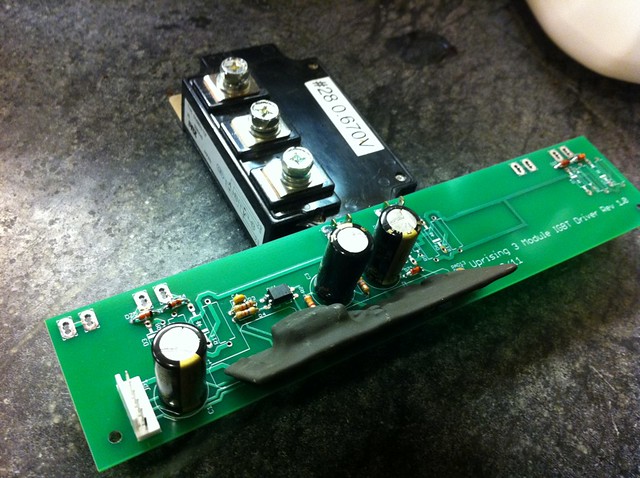 Untitled
 by AdamBrunette, on Flickr
Heres a scope shot of the single 3R3 gate resistor. (Switching at 16kHz)
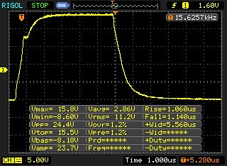 3R3GateOnOff
 by AdamBrunette, on Flickr
After this, I decided to speed up the turn off as much as I could without going overboard. The recommended gate resistor value is 3.1R so I went a little smaller with 3.0R. This is put in parallel with the 3.3R with a ultra fast diode blocking it from being used for turn on. This yield's about 1.57R for turn off. This dropped turn off times from 1.14uS to 720nS. This is still considerably slower then the 250nS fall time in the spec sheet. The spec sheet is talking about switch side and not gate side though. This could all change later today when I connect an actual battery and load motor.
Here is a scope shot of the rise. (Switching at 8kHz)
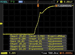 3R3On 3ROff Rise
 by AdamBrunette, on Flickr
Here is a scope shot of the fall. (Switching at 8kHz)
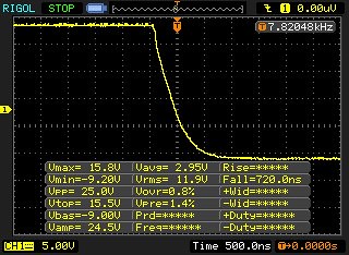 3R3On 3ROff Fall
 by AdamBrunette, on Flickr
On a side note, I have been doing some loss simulation calculations and have found out that in order to get the 1000A out of 3 modules, and keep them from overheating, The controller will have to run at 8khz.
Here are screen shots of 16khz and 8khz. Look at switching loss's for each and junction temp average.
 Screen shot 2011-12-11 at 11.14.14 PM
 by AdamBrunette, on Flickr
 Screen shot 2011-12-11 at 11.14.01 PM
 by AdamBrunette, on Flickr
-Adam |
|
|
|
|
The Following 2 Users Say Thank You to adamj12b For This Useful Post:
|
|
|
12-12-2011, 02:33 PM
|
#17 (permalink)
|
|
EcoModding Lurker
Join Date: Sep 2011
Location: europe
Posts: 43
Thanks: 26
Thanked 4 Times in 3 Posts
|
Nice work ,I am sure you keep away from the little parties scattered here and there at this time, to keep your work in progress.Keep it up.
Thanks.
|
|
|
|
|
12-12-2011, 04:29 PM
|
#18 (permalink)
|
|
Master EcoModder
Join Date: Sep 2009
Location: Ireland
Posts: 734
Thanks: 26
Thanked 304 Times in 171 Posts
|
Don't forget that your gate waveforms will differ greatly when driving the transistors with no load or dc bus than when driving on load. That pesky miller effect really takes its toll!
__________________
Now, Cole, when you shift the gear and that little needle on the ammeter goes into the red and reads 2000 Amps, that's bad.
www.evbmw.com
|
|
|
|
|
12-19-2011, 04:05 PM
|
#19 (permalink)
|
|
Master EcoModder
Join Date: Apr 2009
Location: Charlton MA, USA
Posts: 463
Thanks: 31
Thanked 183 Times in 94 Posts
|
Well I spent some time this weekend tuning the driver board. I ordered new carbon composition resistors and matched them in groups of 4 to make specific high tolerance values.
I first started with 3.0R because I messed up with my meter and didnt offset the lead resistance of 0.1R. Heres a shot of what That looked like on the scope.
 NewFile7
 by AdamBrunette, on Flickr
You can see the turn off was ringing like crazy. It would actually turn the switch fully on with the ring.
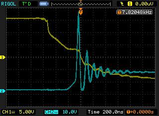
I then went to 3.65R and it started looking alot beter. But im curious why there is still such a large ring... I plan to try 4 parallel 16R resistors for about 4R gate resistance and see if that helps. I want to stay as small as possible because switching loss's are already high enough. I dont want to counter my slower 8khz frequency with long switching times.
 NewFile17
 by AdamBrunette, on Flickr
The turn on of the module has always been pretty good.
NewFile8 | Flickr - Photo Sharing!
Here are the shots of turn on and off with the 3.0 gate resistor. They look pretty good.
Turn on:
 NewFile1
 by AdamBrunette, on Flickr
Turn Off:
 NewFile2
 by AdamBrunette, on Flickr
Heres a longer time withe the gate off for comparasion
 NewFile20
 by AdamBrunette, on Flickr
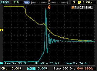
This is where I left it. About 33V spike on turn off. This is down from about 68V!!
 NewFile22
 by AdamBrunette, on Flickr
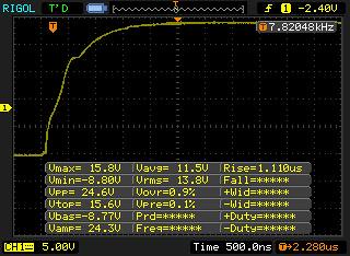
Heres what damien was seeing on his controller. 5V/div 20uS/div
 ce1
ce1 by AdamBrunette, on Flickr
More testing tonight!!
-Adam |
|
|
|
|
12-19-2011, 04:38 PM
|
#20 (permalink)
|
|
EcoModding Apprentice
Join Date: Feb 2010
Location: Northern Wisconsin
Posts: 137
Thanks: 32
Thanked 39 Times in 23 Posts
|
I have used ferrite beads with Bots to quench the ring - that help?
__________________
Dave ...
|
|
|
|
|


