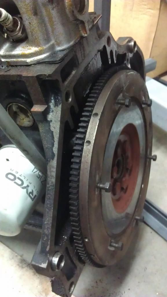
That's the flywheel from a 1.4/1.6L VW Polo.
If memory serves me right it weights about 14KG itself and 18KG with the clutch and pressure plate installed. Add another 3KG to the crank adapter. The motor rotor weights about 25KG.
I removed the ring gear because of clearance issues with my adapter, when I changed from steel to aluminum. To be fair never had any sort of issues with the original one, but my motor is capped at 3800RPM.
Astro,
I drive 10 miles before the coolant pump kicks in so although PWM seems needed, circulating the coolant once a minute does the job just nicelly.
On an ICE the fuel decreases with RPM because for the same throttle opening less air can go into the engine as the admission stroke is shorter. Unless is turboe'd, of course.
On a EV startup torque is quite considerable, but its not linear either, specially as the motor goes into field weakening. Battery sag also plays a factor.
So in reply to your question, yes just like a petrol you get a time when the torque at 30% is just enough to overcome friction, rather than continuing linear delivery. There is some customization one can do with look up tables on my controller, in fact I just had a dead spot on the 10-40% Regen that I just fixed. I'm not sure how Paul setup will work, but technically he can do something similar.
In practice you just need to drive it... like an ICE, except with much more low end torque and limited gear changes

I have that too, although its part of a separate project, done with an arduino mega.


That was an earlier version, that drove the gauges and replaced the odometer. No photos of the newer version sadly.
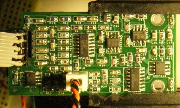
there is also a Texas instruments fuel gauge to report battery status


 Today
Today