Go Back   EcoModder Forum > EcoModding > Fossil Fuel Free > Open ReVolt: open source DC motor controller
Register Now
 Register Now
 

Reply  Post New Thread
 
Submit Tools LinkBack Thread Tools
Old 09-15-2009, 11:15 PM   #2281 (permalink)
EcoModding Lurker
 
Join Date: Jun 2009
Location: Australia
Posts: 35
Thanks: 0
Thanked 3 Times in 3 Posts
Quote:
Originally Posted by LouMan View Post
Kool getting anxious to start building it hehe

any words about ver.d boards on page 226, the upgrades look great!!
let me know when I can order one hehe.
I have posted the PCB files on the WIKI. If you want to order a set, I am about to place an order with PCBCART. It should be about $AUD9 for controller boards and $AUD18 for power boards plus postage.

These will be prototypes and may need some mods. The version C boards are proven.

  Reply With Quote
Alt Today
Popular topics

Other popular topics in this forum...

   
Old 09-16-2009, 12:13 AM   #2282 (permalink)
PaulH
 
MPaulHolmes's Avatar
 
Join Date: Feb 2008
Location: Maricopa, AZ (sort of. Actually outside of town)
Posts: 3,832

Michael's Electric Beetle - '71 Volkswagen Superbeetle 500000
Thanks: 1,368
Thanked 1,202 Times in 765 Posts
Hey Alvin! Yes, shielded cable for the LEM. Attach one end of the ground wire inside the shielded cable to system ground, which is one of the LEM pins.

The engineer that did the first 3 assembled control boards wrote to me about the missing part numbers:


The 4 pin housing that plugs into the controller is 22-01-3047 . The housing that plugs into the LEM header is 22-01-1042.
It's a bit narrower than the other 4 pin (.098" pitch versus .100"). They both use the same crimp pins though.

5 pin Molex 09-50-8053
4 pin Molex 22-01-3047 (to LEM)
3 pin Molex 22-01-3037 (rs-232)

crimp pins for 3 & 4 pin housings above.
08-50-0114 This accepts wire from 22-30AWG

crimp pins for 5 pin housing
08-50-0134 This accepts wire from 22-26AWG
08-52-0072 This accepts wire from 18-24AWG

COULD SOMEBODY ADD THESE TO THE WIKI? I would, but I don't feel like it! hahahaha.
__________________
kits and boards
  Reply With Quote
Old 09-16-2009, 12:29 PM   #2283 (permalink)
Master EcoModder
 
Join Date: Apr 2009
Location: Charlton MA, USA
Posts: 463

EVVette - '71 Chevy Corvette Coupe
Thanks: 31
Thanked 183 Times in 94 Posts
Hi Guys,

I have finally got my controller up and running!!

Here are some pictures and a video of the initial golf cart run!

Assembled Top:


Assembled Bottom:


Control Board:


Internals:

* The little connector sticking up near the B+ bus bar is the thermal sensor sticking out of the heat sink.

Right Side Up with Enclosure Cross Section:


Dual Driver Board:


And the video!!!


I hope you enjoy!!

Sorry for the simple post, I am running out the door now and this is all I had time for.

-Adam
__________________
www.EVVette.com - 1971 Corvette Coupe Conversion to all Electric!
www.AdamBrunette.com - Machining, CNC, Robotics and Electronics.

You can download RTD Explorer for the Cougar controllers at www.EVVette.com
  Reply With Quote
The Following 2 Users Say Thank You to adamj12b For This Useful Post:
deodeo (03-21-2012), mpgmike (01-12-2022)
Old 09-16-2009, 04:37 PM   #2284 (permalink)
Master EcoModder
 
Join Date: Nov 2008
Location: Massachusetts, USA
Posts: 442
Thanks: 1
Thanked 60 Times in 45 Posts
Wow, Adam that is looking good!

Yeah, a golf car isn't going to stress that beast of a controller, unless you try to climb some mini mountains or something.
__________________
Civic EV http://2001-civic-ev.blogspot.com/
Solectria Force http://solectriaforce.blogspot.com/
  Reply With Quote
Old 09-16-2009, 06:47 PM   #2285 (permalink)
EcoModding Apprentice
 
Join Date: May 2009
Location: Australia
Posts: 109
Thanks: 0
Thanked 2 Times in 2 Posts
Adam,
Great stuff. Love your garage!

I'm a bit worried about the mechanical reliability of the MOSFET driver board. What have you done to prevent it from vibrating itself to death? The way it looks in the photos it is likely to get failure of the solder joints.

Other then that it looks like a nice job.
  Reply With Quote
Old 09-16-2009, 10:39 PM   #2286 (permalink)
Master EcoModder
 
Join Date: Apr 2009
Location: Charlton MA, USA
Posts: 463

EVVette - '71 Chevy Corvette Coupe
Thanks: 31
Thanked 183 Times in 94 Posts
The golf cart will pull about 60-90 amps driving around the back yard. I plan on taking to some near by fields for some heavy rolling resistance and try and drive the current up.

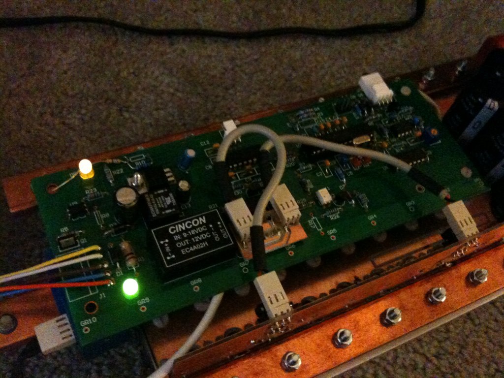
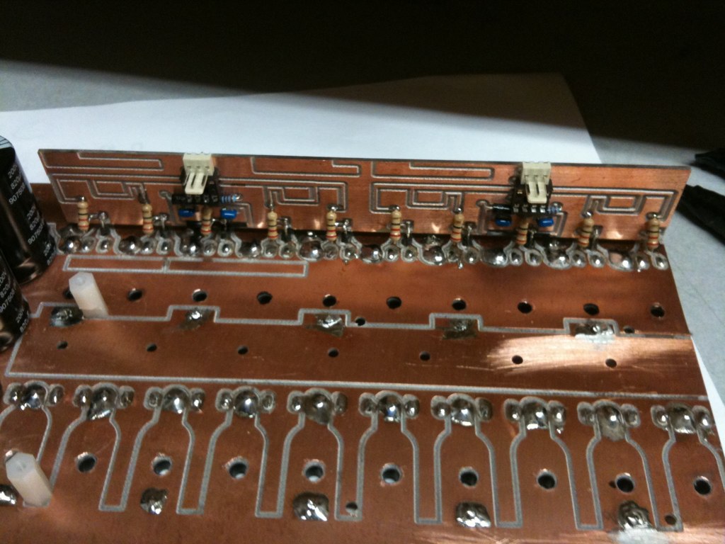
Right now there is only 10 pins connecting the driver board to the power board. I will be increasing this due to needing to reference the driver negative power to battery negative. I am thinking of laying the board down on its side to make the pins only about .1" long and add some more about 1 inch away to support the board.

Right now I have 2 small wires connecting the board to B-, I had to add these for the controller to work, I believe it is due to the inductance. Its not a big fix, just a little one. These wires are actually the ends of some resistors so they are stiff enough to keep the board from moving around.

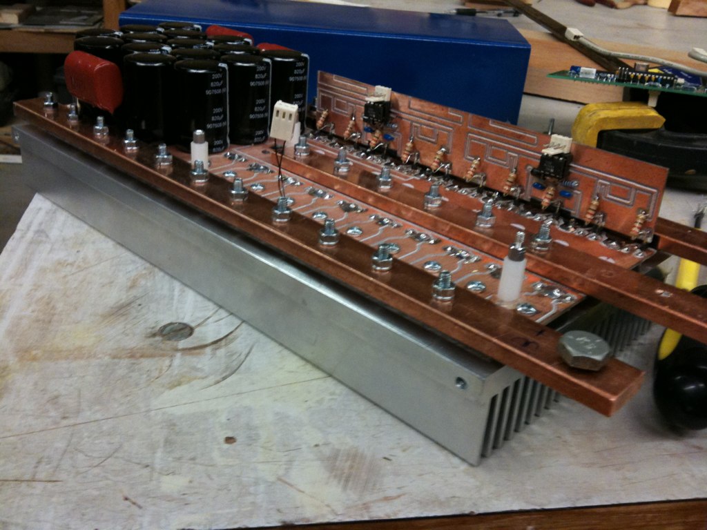
I have also looked into having the power circuit board professionally manufactured. Its looking like $62 plus the tooling fee....., thats about $130.

I also have a few cool additions in the works for the new control boards. I wont go into those now, because I already feel like im taking over paul's thread. I think I will be starting my own thread as to not clutter this one with more unrelated stuff.

As for my garage.......yea......it has seemed to become the catch all for all the stuff left from renovating our house, plus all my machine's and machine parts and motors. I hope to get it cleaned up over the next few weeks. Here are some more pics to show just how bad it is. lol

Overall:


2.5 and 4 HP Servo Motor Collection:


Front of Garage:


Well thats it for now.

-Adam
__________________
www.EVVette.com - 1971 Corvette Coupe Conversion to all Electric!
www.AdamBrunette.com - Machining, CNC, Robotics and Electronics.

You can download RTD Explorer for the Cougar controllers at www.EVVette.com
  Reply With Quote
Old 09-17-2009, 03:04 AM   #2287 (permalink)
EcoModding Apprentice
 
Join Date: May 2009
Location: Australia
Posts: 109
Thanks: 0
Thanked 2 Times in 2 Posts
Mounting the board laying down attached with three nylon standoffs would be a good idea.


Using the electrical connections as support is right at the top of the don't do it list.

Just noticed you are using some standoffs already in your construction. Add some more

Last edited by squiggles; 09-17-2009 at 03:09 AM.. Reason: opened eyes!
  Reply With Quote
Old 09-17-2009, 08:09 AM   #2288 (permalink)
EcoModding Lurker
 
Join Date: Jun 2009
Location: Australia
Posts: 35
Thanks: 0
Thanked 3 Times in 3 Posts
Hey Adam,

That's looking good, but I agree with Squiggles, you need to fasten the control board down and make sure that the cabling does not continuously flex. A car is a very high vibration environment and you can't rely on soldered connections if they are not backed up mechanically. If you are going to solder wires direct to a board the wire should be multistranded and staked to the board using glue (loctite 382 or similar). The other alternative is to use crimped pins into a connector that is attached to the board by screws. You have to think that every connection coming off the board is going to flex millions of times during it's life and the idea is to extend that life as long as possible.
  Reply With Quote
Old 09-17-2009, 02:38 PM   #2289 (permalink)
PaulH
 
MPaulHolmes's Avatar
 
Join Date: Feb 2008
Location: Maricopa, AZ (sort of. Actually outside of town)
Posts: 3,832

Michael's Electric Beetle - '71 Volkswagen Superbeetle 500000
Thanks: 1,368
Thanked 1,202 Times in 765 Posts
Due to the variation in the gain of the HCPL-4504 optocoupler, the BOM needs to change R15 from 330 to 220 Ohm, and R16 needs to change from 3k to 6.8k.
__________________
kits and boards
  Reply With Quote
Old 09-17-2009, 03:24 PM   #2290 (permalink)
PaulH
 
MPaulHolmes's Avatar
 
Join Date: Feb 2008
Location: Maricopa, AZ (sort of. Actually outside of town)
Posts: 3,832

Michael's Electric Beetle - '71 Volkswagen Superbeetle 500000
Thanks: 1,368
Thanked 1,202 Times in 765 Posts
wait... The BOM can't change things. It's an inanimate object.

__________________
kits and boards
  Reply With Quote
Reply  Post New Thread


Similar Threads
Thread Thread Starter Forum Replies Last Post
Paul and Sabrina's Cheap 3 Phase Inverter (AC Controller) with Field Oriented Control MPaulHolmes Fossil Fuel Free 3480 05-04-2022 05:43 PM
Paul & Sabrina's Cheap EV Conversion MPaulHolmes Fossil Fuel Free 542 11-12-2016 09:09 PM
Three Dirt Cheap DIY Electric Cars - Part 5 SVOboy EcoModder Blog Discussion 0 12-12-2008 04:10 PM


Powered by vBulletin® Version 3.8.11
Copyright ©2000 - 2024, vBulletin Solutions Inc.
Content Relevant URLs by vBSEO 3.5.2
All content copyright EcoModder.com