Go Back   EcoModder Forum > EcoModding > Fossil Fuel Free
Register Now
 Register Now
 

Reply  Post New Thread
 
Submit Tools LinkBack Thread Tools
Old 10-13-2009, 03:25 PM   #171 (permalink)
EcoModding Lurker
 
Join Date: Jun 2009
Location: outskirts
Posts: 17
Thanks: 0
Thanked 1 Time in 1 Post
In case you would like to see some guidance in terms of software features for modern chargers, check these made by Piktronik, they are probably the best configurable LV (<1.2kW) chargers out there and quite expensive (obviously apart from Brusa -CH- but these are more into HV and uber expensive). The only criticism so far about Piktronik was minor about only linear type of temp. compensation settings availability.

KOP line of chargers:
PIKTRONIK

page #2 PC settings screenshot:
http://www.piktronik.com/index.php?download=43.pdf

  Reply With Quote
Alt Today
Popular topics

Other popular topics in this forum...

   
Old 10-18-2009, 04:32 PM   #172 (permalink)
Master EcoModder
 
Join Date: Sep 2008
Location: Texas
Posts: 632
Thanks: 0
Thanked 26 Times in 24 Posts
high current inductors from copper tubing? - diyAudio
Looks like at 50kHz or above, you might be able to make the inductor using supplies available from Home Depot. Certainly something to consider for a high current charger.
__________________
If America manages to eliminate obesity, we would save as much fuel as if every American were to stop driving for three days every year. To be slender like Tiffany Yep is to be a real hypermiler...

Allie Moore and I have a combined carbon footprint much smaller than that of one average American...
  Reply With Quote
Old 10-24-2009, 04:09 PM   #173 (permalink)
EcoModding Lurker
 
bones007's Avatar
 
Join Date: May 2009
Location: Brampton, Ontario, Canada
Posts: 15
Thanks: 0
Thanked 2 Times in 2 Posts
In my opinion the active power factor correction is very valuable as it provides three things:

1- It allows much higher charging current from a standard 110V 15A circuit (fully utilizing the 15A available from the supply).

2- Your power meter measures the Volts*Amps not the watts. If the power factor of the charger is only 0.6 than 40% of the electricity you are paying for is not going into your batteries.

3- It creates a charger that can operate from a universal source (ie: 85-250VAC), so if a higher voltage (220VAC) power source is available just plug it in and it will work. The charging circuit could be designed to detect the value of the supply voltage and adjust the charging current to maximize usage of the AC line.


I found an interesting application note from International Rectifier explaining the use of their Active Power Factor Correction IC IR1150.

See:
http://www.irf.com/technical-info/appnotes/an-1077.pdf

Also, there is an interactive design page that can tell you the value of components required for the desired performance of the basic PFC circuit:


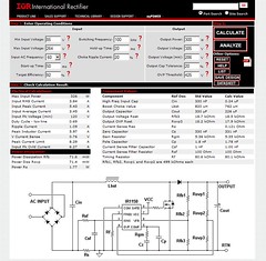
You can get to this design page by creating an account and logging into:
International Rectifier - Design Center
Look for the "Design a PFC Circuit" link.
  Reply With Quote
Old 10-26-2009, 01:30 AM   #174 (permalink)
Master EcoModder
 
Join Date: Sep 2008
Location: Texas
Posts: 632
Thanks: 0
Thanked 26 Times in 24 Posts
No need for a boost converter followed by a buck converter. Do the reverse. Then the inductor can be shared.

And on the link I posted previously, there's a new idea:
Quote:
For the EV charger, maybe some surplus microwave oven transformers can be used as inductors. The switching frequency would need to be reduced, perhaps to the point where cheap standard recovery rectifiers and SCRs can be used. The main disadvantage would be the weight. However, a charger with a power circuit consisting of one large SCR, one large rectifier, and a few microwave oven transformers acting as inductors would be very easy for the DIYer to build.
I remember reading that SCRs are less sensitive to overload than other types of semiconductors. A SCR can block reverse voltage so no need for a separate input rectifier as the SCR is the rectifier. The low operating frequency means the flyback diode can be a cheap standard recovery rectifier instead of a more expensive high speed rectifier. SCRs tend to be very cheap for the power rating. And old microwave oven transformers can be obtained for free with sufficient salvaging work. It won't be the most efficient charger but it would be cheap and easy to build.
__________________
If America manages to eliminate obesity, we would save as much fuel as if every American were to stop driving for three days every year. To be slender like Tiffany Yep is to be a real hypermiler...

Allie Moore and I have a combined carbon footprint much smaller than that of one average American...
  Reply With Quote
Old 10-26-2009, 02:56 PM   #175 (permalink)
EcoModding Lurker
 
bones007's Avatar
 
Join Date: May 2009
Location: Brampton, Ontario, Canada
Posts: 15
Thanks: 0
Thanked 2 Times in 2 Posts
Can you achieve a high power factor using a buck regulator followed by a boost regulator? I agree that boosting the voltage up to something like 350V only to drop it back down to 160 or so doesn't really make sense...however I haven't seen an example of a power factor correction circuit that is not a boost converter.

From my understanding of SCRs: they work by distorting the current waveform from sinusoidal into a sine wave with the first X degrees set to zero. If this is true, the result would be a charger with a low power factor (ie: paying for peak current and getting only a low RMS current into the battery pack).
  Reply With Quote
Old 10-26-2009, 09:30 PM   #176 (permalink)
Master EcoModder
 
Join Date: Sep 2008
Location: Texas
Posts: 632
Thanks: 0
Thanked 26 Times in 24 Posts
If you leave the buck transistor on, it becomes a plain boost converter. If you leave the boost transistor off, it becomes a plain buck converter.
Use hysteresis current mode control with the buck operating on a slightly higher threshold than the boost.

As for the SCR-based charger, it may actually be cheaper to operate.
a quiz about AC power - diyAudio
Quote:
Does the utility wattmeter register the DC component of the power used? (probably not) Someone will have to turn off everything in their house to measure the meter rotation speed with the diode in and out.
...
No!
...
Take the extreme example: If our diode-equipped soldering iron was one of 1000 in a large factory, all connected in the same way, the facility would be consuming a considerable current which could not be registered by the eddy-current motor driving a standard consumer meter, which responds only to the in-phase AC component).
To put it another way: as you say, high I/V phase angle decreases the work done by, in this case, the meter, but the unregistered power is still available for space-heating or whatever, free of charge.
__________________
If America manages to eliminate obesity, we would save as much fuel as if every American were to stop driving for three days every year. To be slender like Tiffany Yep is to be a real hypermiler...

Allie Moore and I have a combined carbon footprint much smaller than that of one average American...
  Reply With Quote
Old 11-02-2009, 02:57 AM   #177 (permalink)
Master EcoModder
 
jackbauer's Avatar
 
Join Date: Sep 2009
Location: Ireland
Posts: 734
Thanks: 26
Thanked 304 Times in 171 Posts
hey guys just a quick question. Whats the status of this project at present? Is there a pcb/ schematic ready?
  Reply With Quote
Old 11-02-2009, 01:40 PM   #178 (permalink)
Joe
 
Join Date: Feb 2009
Location: phx
Posts: 260
Thanks: 0
Thanked 48 Times in 38 Posts
Quote:
Originally Posted by jackbauer View Post
hey guys just a quick question. Whats the status of this project at present? Is there a pcb/ schematic ready?
Sorry, no pcb or schematic at the moment. I got sidetracked with all the motor controller progress and then I focused on building a DC inverter. But, the inverter seems to work, so once the details are worked out, the charger project will resume. All of the new parts are in - I just gotta take the time to make a new power board.

Paul's control board should work nicely with some modifications, if you were to go that route. Mine is very similar with an isolated gate drive system, hall effect current sensor, and an atmel micro. I didn't include the hardware overcurrent stuff since I was able to test the control algorithm at power levels that are actually test-able with basic equipment.

If you make progress of your own, I hope you share!
__________________
ReVolt AZ testing thread:

http://ecomodder.com/forum/showthrea...ting-9325.html
  Reply With Quote
Old 11-20-2009, 11:09 AM   #179 (permalink)
EcoModding Apprentice
 
apowers's Avatar
 
Join Date: Aug 2009
Location: Tn
Posts: 126
Thanks: 14
Thanked 19 Times in 16 Posts
I am using a Bonn charger I put together from microwave and Digi-Key parts. I have
a 120 volt pack so when it gets to 144 volts I have a light dimmer I use to control
the volts while it finishes off the charge. Could Paul's control board be used to do
this? The power section of the controller could be scaled down, maybe 1 mosfet
to control the low side of the DC output.
Thanks
Alvin
  Reply With Quote
Old 11-25-2009, 08:26 AM   #180 (permalink)
EcoModding Lurker
 
Join Date: Nov 2009
Location: Sweden
Posts: 8
Thanks: 0
Thanked 0 Times in 0 Posts
I'm thinking of building my own dc motor controller and a switched battery charger for my future EV. The charger and motor controller both have

1. a large and expensive capacitor bank in parallell with the batteries
2. a large and expensive heat sink
3. a case

So to "upgrade" a motor controller to a combined charger/motor controller I would only need an inductor, a slightly larger heatsink and case, a MOSFET, a diode, a rectifier and some control electronics.

What do you think?

  Reply With Quote
Reply  Post New Thread


Tags
ev charger


Similar Threads
Thread Thread Starter Forum Replies Last Post
Electric car conversion: Project ForkenSwift MetroMPG Fossil Fuel Free 1041 07-28-2014 09:19 AM
Any interest in developing an open source fuel economy gauge/computer? MetroMPG OpenGauge / MPGuino FE computer 182 06-25-2010 07:00 AM
Open source PCB design dcb OpenGauge / MPGuino FE computer 39 04-25-2010 09:18 PM
Open Source electric conversion information bennelson Fossil Fuel Free 8 02-14-2009 11:23 AM
Open Source LEV Controller FrankG Alternative Transportation 1 03-24-2008 03:10 AM


Powered by vBulletin® Version 3.8.11
Copyright ©2000 - 2024, vBulletin Solutions Inc.
Content Relevant URLs by vBSEO 3.5.2
All content copyright EcoModder.com