01-23-2009, 08:42 PM
|
#21 (permalink)
|
|
Losing the MISinformation
Join Date: Oct 2008
Location: Southern Missouri
Posts: 393
Thanks: 15
Thanked 3 Times in 3 Posts
|
Schumacher is a fairly well known name, that's been around a while. With a 144 volt system, maybe split it, and buy two chargers, to be able to charge it overnight???
Can we beat that building them ourselves, Paul???
__________________

The brake pedal is my enemy. The brake pedal is my enemy. The brake pedal... 
|
|
|

|
 Today Today
|
|
|
|
 Other popular topics in this forum...
|
|
|
|
|
01-25-2009, 01:17 AM
|
#22 (permalink)
|
|
Master EcoModder
Join Date: Sep 2008
Location: Texas
Posts: 632
Thanks: 0
Thanked 26 Times in 24 Posts
|
The peak voltage of 120v AC is 170v, which should be plenty for most DIY EVs.
Directly rectify the AC, maybe with a voltage doubler for higher voltage batteries, and then use a buck regulator. Should be easily achievable using mostly off-the-shelf components. Start in current limit mode and switch to constant voltage once desired voltage is reached, then completely turn off after a while (or go into float charge).
__________________
If America manages to eliminate obesity, we would save as much fuel as if every American were to stop driving for three days every year. To be slender like Tiffany Yep is to be a real hypermiler...
Allie Moore and I have a combined carbon footprint much smaller than that of one average American...
|
|
|
|
|
02-14-2009, 11:47 PM
|
#23 (permalink)
|
|
home of the odd vehicles
Join Date: Jun 2008
Location: Somewhere in WI
Posts: 3,882
Thanks: 500
Thanked 865 Times in 652 Posts
|
I believe the most important thing to make a diy on is the CHARGE CONTROLLER
It is easy to make a dumb charger out of most anything, I even made a higher tech version of this thing to desulphate/controlled overcharge bad batteries
3 Dollar Battery Charger
As stated earlier, The trouble with any of the DIYs is we need a
1. SIMPLE
2. Cheap
3. Reliable
4. Safe will be a function of the charge controller
Device that can turn a contactor or mosfet on and off at preset voltage levels, example my pack voltage should be around 76.5v the max overcharge is usually around 81v if I had a simple, cheap and reliable device that could turn the juice on when voltage was below 76.5 and turn it off once it reached a preset max like 80/81v or whatever pleases me at the time (adjustable would be best) we would be a long way toward making existing cheap chargers safer and ones we build more effective and safe.
The next step would be to make a charge controller, I hear there are AC pwm dimmer switches around for lights and other household items (never knew that) if a controller could be setup to trim the pwm dimmer switch or equiv you could easily control charge current and follow a taper pattern. The beauty of any PWM system is that you end up with a pulsing pattern which helps desulphate batteries as well as charge them.
I think this is a more logical 1st step as suitable transformers are in almost every device I can think of, I just trashed out an audio system for someone to get their CD's out and got a boatanchor multi rail power supply with either of the above devices and a simple diode or bridge rectifier I would have a cheap reliable 8 amp multi volt charger.
Another type of charger I have been contemplating is a cap dump charger you need an input cap of high capacity and an output cap of very low capacity, 50/50 pwm oscillation speed determines charge rate (strap ac to large cap 1; unstrap ac and strap large cap to small cap2, cap 2 discharges into battery while cap 1 charges off ac line current through a bridge or diode)
Anyway I think a workable DIY charger is MORE important than a diy motor controller because it is simpler & cheaper to impliment on your own without lots of knowlege, it also seems to be an item that burns out more often as well. Not to mention a decent charge controller DIY could also spill into other things such as renewable solar and wind systems.
Cheers
Ryan |
|
|
|
|
02-15-2009, 12:03 AM
|
#24 (permalink)
|
|
PaulH
Join Date: Feb 2008
Location: Maricopa, AZ (sort of. Actually outside of town)
Posts: 3,832
Thanks: 1,368
Thanked 1,202 Times in 765 Posts
|
Ya, I was suprised just how powerful PWM is. I definitely think it should be a part of a charger. You should make one! That would be awesome. We need a good PWM based charger. Git' R' Done! ya!
|
|
|
|
|
02-15-2009, 12:15 AM
|
#25 (permalink)
|
|
home of the odd vehicles
Join Date: Jun 2008
Location: Somewhere in WI
Posts: 3,882
Thanks: 500
Thanked 865 Times in 652 Posts
|
Quote:
Originally Posted by MPaulHolmes

Ya, I was suprised just how powerful PWM is. I definitely think it should be a part of a charger. You should make one! That would be awesome. We need a good PWM based charger. Git' R' Done! ya!
|
Lol, I am probably just smart enough to cause lots of trouble 
If we went buck it aint cheap
http://www.zahninc.com/sd1.html?gcli...FQxKGgodQCnydA |
|
|
|
|
02-15-2009, 12:35 AM
|
#26 (permalink)
|
|
PaulH
Join Date: Feb 2008
Location: Maricopa, AZ (sort of. Actually outside of town)
Posts: 3,832
Thanks: 1,368
Thanked 1,202 Times in 765 Posts
|
Geeze. That is expensive. That kid on the right looks like he is on a work release from prison. hehe. I'm not one to talk, though. I also look like I just escaped from Jail. Hey, I did just escape! hahaha! Don't tell anyone, though. It's a secret.
|
|
|
|
|
02-15-2009, 01:29 AM
|
#27 (permalink)
|
|
EcoModding Lurker
Join Date: Dec 2008
Location: seattle
Posts: 72
Thanks: 0
Thanked 1 Time in 1 Post
|
Did you get early release....for the long weekend?
I smile every time I see "early release" on school reader boards  |
|
|
|
|
02-24-2009, 11:23 AM
|
#28 (permalink)
|
|
Joe
Join Date: Feb 2009
Location: phx
Posts: 260
Thanks: 0
Thanked 48 Times in 38 Posts
|
Just found this thread...
... and i've been thinking of this project for a while now since I got my car working and am unsatisfied with the high power onboard chargers that are either massive in weight or massive in dollars.
The ultimate goal: I want something that'll pump 20+ amps into my 144V nominal pack when running on 220V, full 3 stage charging that is adjustable for the number of batteries I have or ambient temp, and will run on 110V without changing anything. Well, maybe a current knob to adjust the current down when on lower power lines.
I got so far as drawing up a design using the TI BQ2031 chip to run a power section as a buck converter with PWM, but have no EE basis to validate it (my work/job is all mechanical engineering).
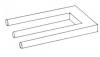
But, I did order all the power section components and have laid them out. My plan is to test this with just a 555 pwm setup sending a signal to the mosfet driver, so essentially I'd have a fancy 'dumb' charger for now if it works. I attached the schematic below - I think it's virtually the same as a motor controller except that it has coil components for added inductance.
There's some big caps for input voltage smoothing from the bridge, another cap across the battery, some large inductors for current smoothing, a diode for clamping the voltage spikes when the FET closes, a large FET acting as a switch, and a shunt to measure current.
The components:
Big 400V caps: $10 each
Big 30A Inductors: $27 each
600V 37A diode: $5
500V 60A FET: $18
600V 40A bridge: $6 (from a surplus site)
Various heatsinks: Maybe $20 worth. I went overkill with just things I had around the house and found at a local surplus shop.
So that's about $140 worth of stuff. Everything else - the control board - shouldn't cost anywhere near that, so we're talking a fairly inexpensive high power charger if this works.
I went overboard with some of the specs since I see nothing wrong with having margin. Also, I can see this project running in stages:
1. Get the powerstage working with just a generic PWM signal (555 timer).
2. Get the control board to successfully control a charging algorithm. (the BQ2031 seems overly complicated - maybe Paul can help with the programing of a custom controller?)
3. (and this is where the high voltage components come in) Build a 300V (or so) Power Factor Corrected power supply that'll supply 300V (or so) to the charger from an AC input from 100 to 250V. This'll allow the charger to run from any typical voltage source AND maximize the power drawn from the power source.
But first things first. Anyone have any comments on this power section schematic? I read up a little on snubbers, but not sure if they're needed or how to implement/design one. At some point, I'll wire all of these up, borrow a scope, and see what happens (i'll start small, maybe just charge a 12V battery running off a 24V transformer).
But, any input is much appreciated!
Joe
|
|
|
|
|
02-25-2009, 01:24 AM
|
#29 (permalink)
|
|
PaulH
Join Date: Feb 2008
Location: Maricopa, AZ (sort of. Actually outside of town)
Posts: 3,832
Thanks: 1,368
Thanked 1,202 Times in 765 Posts
|
Quote:
Originally Posted by jyanof
2. Get the control board to successfully control a charging algorithm. (the BQ2031 seems overly complicated - maybe Paul can help with the programing of a custom controller?)
|
I can help with that! There's no way we need a BQ2031! YA! Way to go Joe! I'll study your schematic more later. I have to do stupid school work right now! Makes me mad, way down deep. $140 for a 144v charger would be really really really nice. |
|
|
|
|
02-25-2009, 08:20 AM
|
#30 (permalink)
|
|
Master EcoModder
Join Date: Jun 2008
Location: London, Ontario
Posts: 1,096
Thanks: 0
Thanked 17 Times in 14 Posts
|
jyanof, can you make a quick description of how the circuit operates? From what I gather, the battery and a 47k resistor are always in series with 240(ish)VDC. Then when the mosfet is on, the battery is then in series with the 2 coils straight to 240... so a pulsing of the mosfet causes a drop in voltage at the negative terminal of the battery (from the 100v or so that the 47k was holding up, down to near 0) and the coils push the current. (I'm no power electronics engineer!)
|
|
|
|
|