01-28-2010, 03:20 PM
|
#21 (permalink)
|
|
Aero Deshi
Join Date: Jan 2010
Location: Vero Beach, FL
Posts: 1,065
Thanks: 430
Thanked 668 Times in 357 Posts
|

Again, Red or Green?
|
|
|

|
 Today Today
|
|
|
|
 Other popular topics in this forum...
|
|
|
|
|
01-28-2010, 03:32 PM
|
#22 (permalink)
|
|
Quest for a 400 mile tank
Join Date: Jul 2009
Location: West Michigan
Posts: 50
Thanks: 43
Thanked 15 Times in 10 Posts
|
The shape I'm using is what most of the other streamline templates on this forum have used. It originates from aerohead's photo album called "perfect streamlined shape". I haven't used the simpler "clock face" shape which is very close.
Fuel Economy, Hypermiling, EcoModding News and Forum - EcoModder.com - aerohead's Album: Book illustrations - Picture
I'm sure the exact shape, give or take a degree is just nit picking. These shapes are basic guidelines for those that haven't studied aerodynamics. My one semester of Fluid Mechanic only gets me a little dangerous.
I cropped your image and scaled it keeping perfect proportions to the template I'm using. I think your scale might be just a bit off.
 |
|
|
|
|
01-28-2010, 04:53 PM
|
#23 (permalink)
|
|
Master EcoModder
Join Date: Jan 2008
Location: Sanger,Texas,U.S.A.
Posts: 15,883
Thanks: 23,957
Thanked 7,219 Times in 4,646 Posts
|
Cont'd from yesterday
Quote:
Originally Posted by aerohead

(1) Yes,the longitudinal centerline constitutes the ground plane and the vehicle would be scaled to fit with it's wheels on the "ground",and the highest point of the roof aligned with the 12:00 O'clock position.The rest of the roofline is defined by the curve.
(2) The very back of the teardrop is the separation point,so all points ahead of that are in attached flow.
(3) Since all vehicles must have ground clearance,it would be impossible(and unnecessary ) to build a body the full length of the drop,as it would end where intersected by the belly line.
Al is closing the store,I've got to close now,will catch up asap.
|
I'm trying to pick up where I left off yesterday,but all the original graphics and questions didn't get included in the new"quote".
(3)(cont'd) This 'clock-face' template is more liberal than the "Aerodynamic Streamlining Template",at about 2.78:1 L/D ratio as opposed to 2.5:1.And with the hemispherical nose instead of the prolate ellipsoid,it has more aftbody.It's more akin to the one Darin first posted with "Permanent Metro Kammback." They all will provide attached flow.The 2.5:1 has the least drag,with lowest friction drag,as it has the least "wetted-area"(i.e. skin friction).
The spirit of the clock-face template,is that,in light of it's origins,it could be used with an extremely high degree of confidence to construct a roof-line of any length(or boat tail or trailer )which maintains attached flow,working with virtually no other reference.
This line of reasoning was the foundation for Kamm's,von Fachsenfeld's,Jaray's,Klemperer's,Lay's,Heald's,Re id's,and others development of low-drag cars,including Hucho,for the VW 2000 concept.
Today,university teams are using this form to win solar car and HPV competitions,whether on land or underwater. |
|
|
|
|
The Following User Says Thank You to aerohead For This Useful Post:
|
|
|
01-28-2010, 05:01 PM
|
#24 (permalink)
|
|
Master EcoModder
Join Date: Jan 2008
Location: Sanger,Texas,U.S.A.
Posts: 15,883
Thanks: 23,957
Thanked 7,219 Times in 4,646 Posts
|
Green
Quote:
Originally Posted by ChazInMT
OK here's a response, with graphics.
I guess it's more of a question,
You state somewhere in here that the wheels of the vehicle should rest on the ground plane.
Yet you say that flow separation occurs at 4 seconds after midnight.
It seems to me that these 2 statements contradict in the sense that air will either remain attached to a given shape until it reaches 4 seconds past midnight (115° beyond stagnation) on a curve (Red), or, you need to overlay a huge wing section onto a given vehicle (Green), and if you fall below this line at any point, you have flow separation, even if it occurs at some point less than 115° (which in this case is on the ground 20 feet behind the truck).
Which one is it? Red or Green? Or am I missing something? (Again, as usual)
 |
For this template,it would be the green.It's "clean" but LONNNNNNNNNNNGGG!
For this reason I prefer the 2.5:1.
|
|
|
|
|
01-28-2010, 05:13 PM
|
#25 (permalink)
|
|
Master EcoModder
Join Date: Jan 2008
Location: Sanger,Texas,U.S.A.
Posts: 15,883
Thanks: 23,957
Thanked 7,219 Times in 4,646 Posts
|
template,sides,Cd
Quote:
Originally Posted by ChazInMT
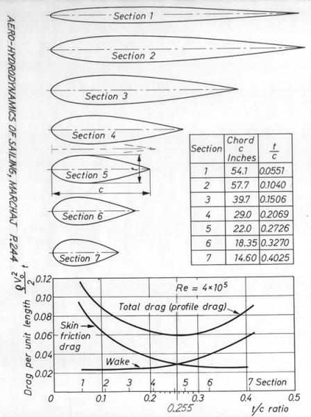
The question I have with your dark red is that it is scaled to the size of the vehicle. I think that as long as we're talking about largish objects like cars, trucks, boats & motorcycles, the 115° flow separation rule applies. So as long as we keep our top radius line from going past that 115° point, it really doesn't matter the shape. The reason we use this particular template is that it has the best "surface area/ wake generation" ratio. The segment we use is very similar to section 5.
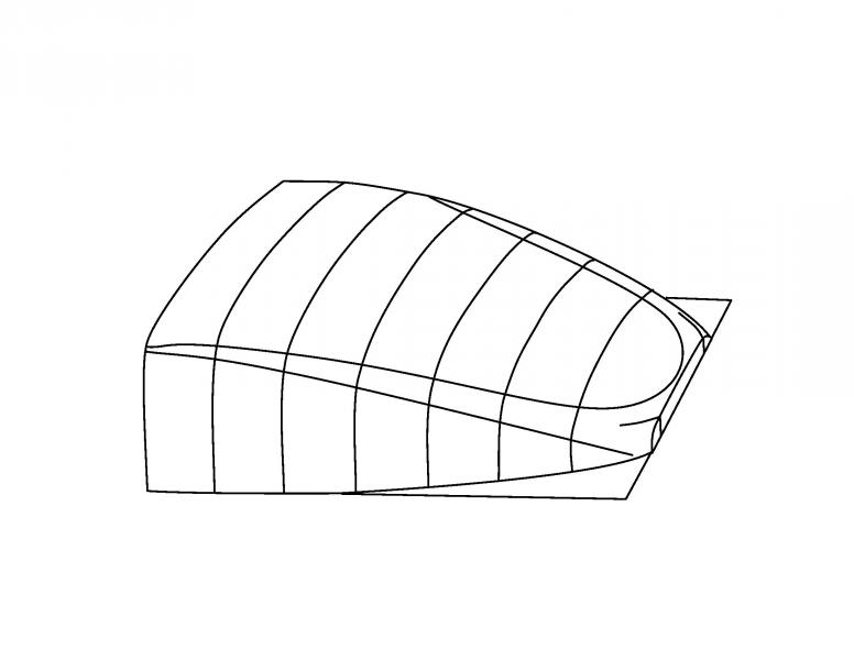
This brings up another point that I think people don't often consider. We spend a lot of time trying to make the tops of our vehicles as aero as possible, and often neglect the sides. The air moving around the sides of our trucks and cars has a large impact as well I say. On my Pickup, the sides are about 22" tall on the passenger cabin, just in front of the bed. The roof width at the top in this area is about 52" so with 2 sides at 22", that's 44" of air surface. So we worry about 55% of the equation and neglect the other 45%. This is why I have designed a taper in the sides of my aerocap when viewed from the top. Doing this results in a fastback design.
More food for thought....It is often said that the best possible Cd we can achieve is .18 based on the .09 holy grail of aero shape in ground effect...The sides of the vehicle are not in ground effect. ") Hmmmmmmmmmm.
 |
From the strut chart you see that the drag minimum occurs where form drag minimum intersects the skin friction drag minimum at t/c 0.255,somewhere between shape #4 and #5.These are 2-dimensional flow devices and in 3-dimensions,the minimum appears around L/D 2.5:1
With respect to the sides,BINGO!!!!!!! This is exactly what Kamm was doing with the roofs of his K-Cars,and is the reason your cap will have lower drag.
As far as the Cd minimum,Subaru,and GM(AeroVironment) have demonstrated sub-0.10 forms.
|
|
|
|
|
01-28-2010, 05:55 PM
|
#26 (permalink)
|
|
Master EcoModder
Join Date: Jan 2008
Location: Sanger,Texas,U.S.A.
Posts: 15,883
Thanks: 23,957
Thanked 7,219 Times in 4,646 Posts
|
my mind
Quote:
Originally Posted by Christ
Phil -
I gotta be honest here; I'm not entirely sure I understand exactly what is going on in your mind with this one.
I'm desperately trying to follow, but from what I can tell, your pattern (it's yours, right?) suggests that for attached flow, we'd need something along the lines of a 30 foot long vehicle with a bull nose, which doesn't seem to follow the logic of a 3:1 relationship between length and frontal area.
Could I trouble you to elaborate a bit more?
EDIT: I think I understand a little bit better, after having re-read the text and taking a more detailed look at the images. I do, however, still have a question - since the profile of the divine shape is a curve, at what point do we measure the angle of descent?
I notice in your image that it states a 22* angle at approximately 1/4 of the distance from the tail tip to the "12 o'clock", or the area at which cross sectional diameter is the largest. Is that the proper measurement there, or do we average the slope of the full form against the flat center line?
Also - does this apply as is to a land-vehicle, when given the ground effect?
|
Christ,This thing is just a thought experiment.The "dimple-hysteria" got everybody obsessing over golf-balls,spheres,laminar and turbulent boundary layers and drag.
The sphere seemed the perfect tool to introduce what would morph into wing theory,fuselage theory,and finally automotive body theory.
The 'clock-face' is a SURE THING.But that's not to say that I's use it.
For attached flow,you need at least the aft-body portion of the 2.5:1 teardrop.It can be longer but the drag will be higher due to increased skin friction.
Will the skin-friction increase make a big difference? No! Skin friction is only about 7% of the overall aerodynamic drag of an automobile.So even if aggravate it with a lot of wetted-area,the overall net increase is negligible.I'm sure Bicycle Bob wanted to throw knives at me when I first introduced the template with 2.5:1 L/D ratio due to it's "shortness".Stretching a body out l-o-n-g-e-r wouldn't really beat you up at the gas pump.
I just wanted to build a consensus on theory which states that there is a point where profile drag and skin friction,together,present the lowest drag,which to the best of my abilities occurs for a body of revolution of 2.5:1 L/D.
As to the 30-foot-long thing,for my T-100,this IS about the length I'll need to hit Cd 0.12 or lower,due to it's height and width,and is why I chose to go the trailer route.A 7-foot boat tail seemed out of the question.By adding some length,I get a trailer I can camp with,and it looks like the trailer will pay me to pull it.
If you have Hucho's book,or have access to it,when you look at Jaray's ground-reflection for a body of revolution in ground-effect,which was the basis of his 1922 Cd 0.13 design,it looks eerily similar to the clock-face segment in reflection which creates the template.Also Kamm's development model for his K-Cars. |
|
|
|
|
The Following User Says Thank You to aerohead For This Useful Post:
|
|
|
01-28-2010, 06:05 PM
|
#27 (permalink)
|
|
Master EcoModder
Join Date: Jan 2008
Location: Sanger,Texas,U.S.A.
Posts: 15,883
Thanks: 23,957
Thanked 7,219 Times in 4,646 Posts
|
teardrops
Quote:
Originally Posted by ChazInMT
MJ, I am using exactly what Aerohed described. I have analyzed the shape you posted here and have the results below. I hope it makes sense.

In this image I have placed your teardrop ideal and the ideal that Aerohed presented earlier. Your shape is the bright green one in this image. My shape is red. I have been extremely careful not to mess with any of the proportions of these shapes at anytime. Also, I have made a circle in my drawing program and have marked a point which is 25° past center and then I trace this shape to get my template, I did not simply trace Aeroheds foil shape.

In this image I have overlaid my shape (bright green) with the foil cross sections which I got from somewhere. You can see that my shape closely approximates the shape # 5 on this chart, your shape (red) is pretty close to #7.
I have noticed that the nose shapes on Aeroheds foil, your template, your ideal foil, and these foils on the chart are all quite different. This I suppose could be the subject of a new discussion. |
The lower teardrop image within streamlines is from Baron R. von Fachsenfeld.This drop has a L/D ratio of about 2.72:1 which is a little longer than what is necessary.
Your green line drop would have the lower drag.
|
|
|
|
|
01-28-2010, 06:14 PM
|
#28 (permalink)
|
|
Master EcoModder
Join Date: Jan 2008
Location: Sanger,Texas,U.S.A.
Posts: 15,883
Thanks: 23,957
Thanked 7,219 Times in 4,646 Posts
|
green
Quote:
Originally Posted by ChazInMT
Again, Red or Green?
|
With this template,the green outline would be proper.This does not suggest it is the lowest drag,only that it will be free of separation.Personally,I would not choose it.
|
|
|
|
|
01-28-2010, 08:23 PM
|
#29 (permalink)
|
|
Aero Deshi
Join Date: Jan 2010
Location: Vero Beach, FL
Posts: 1,065
Thanks: 430
Thanked 668 Times in 357 Posts
|
Aerohed, the red and green templates are both based exactly on the clock face template you described. I made a circle, found its exact center, then projected a line from the center at 25°. I then traced that shape. This yields the templates I made.
I just analyzed these further and found some stuff out.

If I make a teardrop out of your "4 Seconds" diagram, I get a 2.75:1 shape using a semi circle as the front. The circular section on top travels through 25°. (Red)
If I make a teardrop that is 2.5:1 using a semi circle front, it yields a top circular section that travels 28° or 4.5 seconds after midnight. (Blue)
More questions & graphics later, I would like to nail this down pat as I'm sure many who are looking in on this would.
Last edited by ChazInMT; 01-29-2010 at 12:23 AM..
|
|
|
|
|
01-29-2010, 12:00 AM
|
#30 (permalink)
|
|
Moderate your Moderation.
Join Date: Nov 2008
Location: Troy, Pa.
Posts: 8,919
Pasta - '96 Volkswagen Passat TDi 90 day: 45.22 mpg (US)
Thanks: 1,369
Thanked 430 Times in 353 Posts
|
Phil -
Excellent answer, and very helpful in understanding the purpose of your idea.
Looking at Chaz's images, would the smaller half-drop shapes be ideal for kamm extensions (in profile view only), or could the Kamm extension yield a higher angular slope?
__________________
"¿ʞɐǝɹɟ ɐ ǝɹ,noʎ uǝɥʍ 'ʇı ʇ,usı 'ʎlǝuol s,ʇı"

|
|
|
|
|