 05-16-2013, 07:21 PM
|
#31 (permalink)
|
|
...beats walking...
Join Date: Jul 2009
Location: .
Posts: 6,190
Thanks: 179
Thanked 1,525 Times in 1,126 Posts
|
...sorta makes the K.I.S.S. "string & plumb-bob" idea look much better?
|
|
|

|
 Today Today
|
|
|
|
 Other popular topics in this forum...
|
|
|
|
|
05-17-2013, 07:15 AM
|
#32 (permalink)
|
|
Master EcoModder
Join Date: Apr 2013
Location: World
Posts: 385
Thanks: 82
Thanked 82 Times in 67 Posts
|
Quote:
Originally Posted by Nevyn

Why not get one of these?
|
Because, like the other suggestions we've come up with, from 5 cent pendulum to $100 Arduino plus accelerometer but minus speed input, it won't measure slope in a moving vehicle. They will all be measuring the slope plus some component or all of whatever acceleration the vehicle is subject to.
It's easiest to describe using the pendulum device. Stop on a slope and the pendulum will be at some angle relative to the car. Accelerate away from rest and the pendulum will swing towards the back of the car, no longer indicating the slope.
What is needed is a way to determine the acceleration of the car relative to the road and subtract that acceleration from the total acceleration (along the slope; x direction) to leave the gravitational component. It will be possible to do that with the Arduino. I expect it would also be possible with the G-Whiz, a speed sensing input and some analog computing but the Arduino will be easier. |
|
|
|
|
05-17-2013, 07:31 AM
|
#33 (permalink)
|
|
Master EcoModder
Join Date: Apr 2013
Location: World
Posts: 385
Thanks: 82
Thanked 82 Times in 67 Posts
|
Quote:
Originally Posted by jeff88
Build one!
|
Maybe but you've drawn me into building an Arduino based one now. (I had to buy only the prototype board and some connectors.)
Quote:
|
I'm still a little lost, so I'm not sure what you mean by integrating the acceleration #s, adding mass and KE and PE. I would like the inclinometer output, but if these numbers can give me other useful information, I would be open to looking into it.
|
That's probably trying run before walking but it's feasible.
Integration in the mathematical sense. If you have acceleration you can sum that over time to get velocity or measure the (x-direction) velocity directly with the speed sensor input. With x-direction velocity, KE=(m x v^2)/2.
Integrate velocity you have displacement. Use z-direction displacement to get PE=m x g x h. Where m = mass, v=velocity, g=gravitational acceleration, h=height from an arbitrary reference.
I can explain it further but maybe we should wait until the basics are sorted. |
|
|
|
|
05-17-2013, 11:59 AM
|
#34 (permalink)
|
|
Master EcoModder
Join Date: Apr 2013
Location: World
Posts: 385
Thanks: 82
Thanked 82 Times in 67 Posts
|
Quote:
Originally Posted by jeff88
So will this little gizmo work for what I want, or will it not take into account different accelerations? In other words, will it display the incline or will it add in lateral or horizontal accelerations, throwing off the number?
|
The Arduino based gizmo? I expect it will at least read and display the 3 acceleration values. The $100 pendulum  . (That's for Old Tele Man).
If you can get the VSS input and convert that to an x-axis acceleration, the Arduino unit will also read the incline. There will still be some error from the transverse slope of the road.
Quote:
|
So that gizmo won't work and I need to build my own board to subtract out different accelerations?
|
Whatever it is, it has to separate out the vehicle acceleration from that due to gravity. Nothing proposed so far other than the Arduino (and possibly a G-Whiz with a speed input - how though???) can do that.
Quote:
|
I'm willing to do the work, I just need to know what to do! If I get instruction '1) do this 2) do this 3) do this' then I can do it. After I do it once, I am pretty good at figuring out how to do it in less structure and can even come up with better ways sometimes. But this being my first time, I need the structure.
|
It's a unique project (AFAIK) so you will have to figure at least some of it out yourself. I don't want an inclinometer but a g-meter I can use and some of the problems involved in getting an inclinometer to work are the same as those in getting PE and KE calculated (which I do want). I will input what I can, if that's worth anything. It's possible that some things won't work it's also possible that it won't work at all. (I hope not, I think not but...)
There's no harm in planning it out (as you appear to be doing) before committing to it and you can do it in stages. (Like get the g-meter part working and being prepared to stop there, if that's as far as it will work.)
Quote:
|
Will a three-axis be enough, or should I get two boards to measure 6 different axes?
|
One linear 3-axis is enough. 6 axis refers to also measuring the rotation (angular acceleration) about each of the 3 axes in addition to the 3 linear accelerations. Adding or using one of those may be an alternative to the speed input to get the incline output.
Quote:
|
Sorry, are you talking about the shield boards, the Mega/UNO boards or the ADXL3xx accelerometer boards?
|
The ADXL3xx (or similar) boards.
Quote:
|
So this says +/-3g. Would that work for me, or is that still a little too much for this application?: Triple Axis Accelerometer This one has a selectable amount +/-2,4 or 8g: Selectable Triple Axis Accelerometer This one can be selected for +/-1.5g or +/-6g: +/-1.5g Accelerometer
|
I think +/- 1.5g or maybe +/- 2g will be best (at least in terms of spec.). What I have is +/- 1.5g so you can wait and see how well that works if you want to. I doubt that more than 1.5g is needed, +/- 3g almost certainly not.
The output voltage maps against the g reading, so if you have a board capable of reading +/- 10g (say, for easy math) with a full scale voltage output of 3.3V and you measure +/- 1g you will only ever use 0.33V of that range. That in itself will reduce the precision of the result.
When that voltage is fed into one of the analog pins on an Arduino, you lose more. They map 0-5V against a 9 digit binary number i.e. 1024 discrete values. 0.33V/5 x 1024 = just 61 discrete values to cover 2g (= +/-1g). The lowest g range that will not be exceeded is best.
Quote:
|
I assume you mean something like this?: I2C Adapter
|
The reason I mentioned I2C is that some of the accelerometer boards put out an I2C data signal instead of the voltages and I don't want you to buy the wrong type by mistake. I haven't looked very hard at what is required to get it to work.
Quote:
|
I have found a ton of screens, so I will get one that is "good" and will fit my needs (meaning size). I want one separate from the board, so I can put the board wherever I want and the screen somewhere in/around the dash.
|
Sounds good.
Quote:
|
I know the board offers 5V and 3.3V, but is one better than the other? What would be a reason why I would choose one or another? Not sure what you mean about the rest. Power to the accel. board with sensors x, y and z relaying voltage based on readings to the Arduino board? Doesn't the Arduino then use those voltages to do the math and display the answer? Or are you saying that a second option is to have the accel directly attached to the display, skipping the Mega/UNO board?
|
You feed the accelerometer board 3.6V-5V (or whatever the data sheet says). The 5V is regulated on the board down to 3.3V, which is what the IC uses. Where it gets 3.6V-5V doesn't matter. You could simply power the accel. board and use a voltmeter to read the output. It would give an output that is proportional to the acceleration the axis (or axes) you are measuring sees, in mV, but that's it.
Quote:
|
So the Arduino will read varying voltages from each sensor on the accel. board, do the math and display it for me?
|
Yes.
Quote:
|
That means I need power to the Arduino board, accelerometer and the display?
|
You need to provide power to the Arduino, within the voltage range specified for it. The regulated voltage on the Arduino is used to power the accelerometer and the display. Look at the wiring schematics in the tut examples.
Quote:
|
I'm thinking a few diodes with a voltage drop across them will get me to the desired voltage for the board, maybe with a relay to help protect the circuitry?
|
Yep. Nice thinking with the diodes. You will need about 6 to get near 9V. 1N4004's should work. The Arduino will probably accept a voltage up to 20V, so you could actually use an ignition source directly but, depending on the current drawn by the Arduino and what is attached to it, the voltage reg. on the Arduino has to work harder than is ideal to dissipate the unwanted voltage (as heat).
Quote:
|
Or I can do something like this? It will input 3-40V and output 1.5-35V.
|
If you want. That may be overkill though.
Quote:
|
Although for learning purposes, the UNO might be easier, I'm wondering if I want the Mega so I can use the board for all my projects with one board instead of two or more. My only concern would be if the Mega is powerful enough to run all of it at the same time and be able to do the calculations fast enough for each project. I would hate for the incline part of the board hog up memory and slow down opening the grill block or bumping up the electric water pump and my engine overheats.
|
Processing speed is less an issue than filling the Atmega chip's memory or having insufficient pins to get the inputs and outputs.
Quote:
|
So with lcd.print, will I get the x, y and z #s or the #s that the Arduino spits out after doing the math for those #s?
|
Read the tuts and the various examples. It will become clear.
Quote:
|
OK, so the voltage that each sensor sends to the unit will translate into a vector, which, with some math I can translate into slope.
|
The voltages each represent a component vector of the total acceleration vector. The math is just translating it into something that makes sense to you.
Quote:
|
What about the opposites? Back, left and up?
|
The voltages are all positive but will be translated into negative numbers, with an offset, to show the direction. Read the tronixstuff tut using the temp. sensor. That's what you'll be doing for each of the 3 accelerometer voltages. A temp. below 0 is similar to a negative acceleration.
Quote:
|
I'm thinking I will set the accelerometer on a construction level, make sure it's flat and then calibrate it. After that, I can install it into the car and be on my way with some slight tweaking.
|
If you are going to try to physically match the accelerometer axes to the car axes, it has to be set up while attached to the car. You don't have to line up, say, the x-axis on the accelerometer with the x-axis on the car. You can rotate it 90 degrees (to match the y-axis) and then fix it in the sketch. You do have to line up (or correct in the software) an axis to the car axis.
Quote:
|
So if the current reading for x,y and z says lets say 1,2, and 3, then I will subtract 1,2 and 3 from their respective sensors in the Arduino sketch and from there on out, the system will know to subtract those numbers from any readings.
|
Conceptually, yes.
Quote:
|
I'm wondering if I should do this with the accelerometer set in position and the car as flat as possible (maybe I can use a jack), this way the calculations/readings are as accurate as possible.
|
Yes. Pointing directly fore-aft and laterally also.
Quote:
|
Sorry, how does this relate?
|
It's the math required to shift the coordinate system of the accelerometer to line up with that of the car, if they don't do so physically.
Quote:
|
So more math to convert from radians to degrees!
|
Only if want the display to read in degrees. Otherwise you use radians within the sketch. It's easy anyway; pi radians is 180 degrees.
Quote:
|
So run a wire from the VSS to an input into the board and in the Sketch use: pulseIn(VSS #)? If necessary, I might need a square wave converter somewhere in that wire before the board input?
|
It depends on what type of speed sensor you have. If you are lucky you will have a Hall sensor type which will already have a 50% duty cycle square wave output. If you are really lucky, it will even be 0-5V. The other common type of sensor uses an inductive pick up which generates a Sine wave that varies voltage and frequency with speed. That one will need to be converted to the square wave. A 555 based circuit might do to do that.
There is often more than one speed signal. The ECU will have one, usually the raw signal, but if the speedometer is electronic there will be a signal there also. One of them is likely to be a processed, square wave, signal.
Quote:
|
This? There are cheaper ones, but this one is specifically for Arduino, does it matter?
|
You don't want to generate a signal, just process it (then only if necessary).
Quote:
|
How do I determine if the VSS is outputting a square wave, will a multi-meter be able to do that for me? And why does the VSS need to output in square wave to work for me?
|
Shop manual? You can get some signal info. using a multimeter. A 0-5V square wave signal with 50% duty cycle will show as ~2.5V when measured as direct current. An inductive pick up type will generate an alternating current so you will be able to measure it that way.
A Hall sensor will have 3 wires to it: power, earth, signal. An inductive pick up will have two wires.
It needs to be a square wave to use pulseIn() because you will measure the time that a number of pulses remain high (or low), sum them, divide by the number of samples and double it. That's time for one period of the wave. From that you can calculate the frequency. With the number of pulses per shaft rotation together with the gearing and tire circumference you can get the road speed. Take two sequential speed (velocity) readings a known time apart and you can calculate the acceleration (if there is any).
I haven't looked, but how does MPGuino measure the speed input for your car?
Last edited by Occasionally6; 05-17-2013 at 12:43 PM..
|
|
|
|
|
05-17-2013, 03:27 PM
|
#35 (permalink)
|
|
Not Doug
Join Date: Jun 2012
Location: Show Low, AZ
Posts: 12,186
Thanks: 7,225
Thanked 2,217 Times in 1,708 Posts
|
If nothing else, until you can get your project to work, you can use it as a pendulum!  |
|
|
|
|
05-17-2013, 09:49 PM
|
#36 (permalink)
|
|
Lots of Questions
Join Date: Jan 2013
Location: San Jose
Posts: 665
Thanks: 343
Thanked 101 Times in 79 Posts
|
Quote:
Originally Posted by Occasionally6
Maybe but you've drawn me into building an Arduino based one now. (I had to buy only the prototype board and some connectors.)
|
Oh oh... did I start something here?! It might actually be helpful if you build one, so we can both test, verify and troubleshoot. Unfortunately for me, I have a much larger learning curve, not ever doing this before and not even having any of the pieces.
Quote:
Originally Posted by Occasionally6
One linear 3-axis is enough. 6 axis refers to also measuring the rotation (angular acceleration) about each of the 3 axes in addition to the 3 linear accelerations. Adding or using one of those may be an alternative to the speed input to get the incline output.
|
So I can do a single 3-axis board with the VSS or 2 3-axis boards if I cannot get the VSS to work? If that is the case, I might just do 2 3-axis boards, so I don't have to mess with any vehicle parts directly.
Quote:
Originally Posted by Occasionally6
I think +/- 1.5g or maybe +/- 2g will be best (at least in terms of spec.). What I have is +/- 1.5g so you can wait and see how well that works if you want to. I doubt that more than 1.5g is needed, +/- 3g almost certainly not.
The output voltage maps against the g reading, so if you have a board capable of reading +/- 10g (say, for easy math) with a full scale voltage output of 3.3V and you measure +/- 1g you will only ever use 0.33V of that range. That in itself will reduce the precision of the result.
When that voltage is fed into one of the analog pins on an Arduino, you lose more. They map 0-5V against a 9 digit binary number i.e. 1024 discrete values. 0.33V/5 x 1024 = just 61 discrete values to cover 2g (= +/-1g). The lowest g range that will not be exceeded is best.
|
OK, I'll see what happens with your setup to see if 1.5 or 2g is better. If worst comes to worst, I'll take a little less accuracy and get a 2g, but I won't go higher than that (other than a switchable board). I think I get what you're saying. With a larger spectrum of voltages being sent to the main board, the board can better determine what the actual # of Gs is. With a larger spectrum, .33V and .34V will be vastly different in the output #.
Quote:
Originally Posted by Occasionally6
The reason I mentioned I2C is that some of the accelerometer boards put out an I2C data signal instead of the voltages and I don't want you to buy the wrong type by mistake. I haven't looked very hard at what is required to get it to work.
|
Does this one from the parts list output in I2C or in voltages? I couldn't find out from the datasheet provided. 3-Axis Accelerometer
Quote:
Originally Posted by Occasionally6
You feed the accelerometer board 3.6V-5V (or whatever the data sheet says). The 5V is regulated on the board down to 3.3V, which is what the IC uses. Where it gets 3.6V-5V doesn't matter. You could simply power the accel. board and use a voltmeter to read the output. It would give an output that is proportional to the acceleration the axis (or axes) you are measuring sees, in mV, but that's it.
You need to provide power to the Arduino, within the voltage range specified for it. The regulated voltage on the Arduino is used to power the accelerometer and the display. Look at the wiring schematics in the tut examples.
|
According to the datasheet for the Accel. 3.6V is the maximum voltage it will accept. So I guess when I run power to the Mega/UNO, I will run the wires from the battery through the diodes into the Vin header. Then I will run a wire from the 3.3V header to the Accel. Does that sound right?
Quote:
Originally Posted by Occasionally6
Yep. Nice thinking with the diodes. You will need about 6 to get near 9V. 1N4004's should work. The Arduino will probably accept a voltage up to 20V, so you could actually use an ignition source directly but, depending on the current drawn by the Arduino and what is attached to it, the voltage reg. on the Arduino has to work harder than is ideal to dissipate the unwanted voltage (as heat).
|
I can't take credit for the diode idea. I stole (borrowed) it from Echo-Francis who did the same with his Electric Water Pump. So from what I've read, the 1N4004 will have a voltage drop of about .7V. Is that correct? That means that with 6 diodes (wired in series?), the voltage will drop from battery voltage from 12.6 (assuming fully charged) down to 8.4. That is in the operating range specified, but is that too many diodes? Maybe if I use 4 diodes to get me under 10V, that might be better?
I'd rather put in a few diodes, so I don't accidentally overload the circuits... cheap insurance.
Quote:
Originally Posted by Occasionally6
Processing speed is less an issue than filling the Atmega chip's memory or having insufficient pins to get the inputs and outputs.
|
Sorry, yes I meant memory. The Clock Speed on both are the same. The memory, however, is vastly different. The Mega has 8 times the flash memory and 4 times the SRAM and EEPROM. Not sure what of the three I should be more worried about, but the Mega is by far a better board. The Mega, of course, has a much larger amount of pins, which could be useful. I wonder if I need to spend the extra $12 for all the "goodies" though. Certainly with more projects on the horizon, the measly $12 will be cheaper than having to buy a second and third board, but is it really necessary? (That is more a rhetorical question, but any insight/personal experience is still appreciated)!
Quote:
Originally Posted by Occasionally6
The voltages are all positive but will be translated into negative numbers, with an offset, to show the direction. Read the tronixstuff tut using the temp. sensor. That's what you'll be doing for each of the 3 accelerometer voltages. A temp. below 0 is similar to a negative acceleration.
|
OK, that's what I though it might be, just wasn't sure. Somehow in the Sketch, I will have to determine how a negative or positive number reflects in an up slope or down slope. Yay, more math!
Quote:
Originally Posted by Occasionally6
If you are going to try to physically match the accelerometer axes to the car axes, it has to be set up while attached to the car. You don't have to line up, say, the x-axis on the accelerometer with the x-axis on the car. You can rotate it 90 degrees (to match the y-axis) and then fix it in the sketch. You do have to line up (or correct in the software) an axis to the car axis.
|
Yeah, I kinda realized as I was typing, it will need to be in the car during calibration. I should have deleted the construction level part. Wouldn't it be easiest to have the accel. just be in the correct position, so I don't have to do any other fancy work in the Sketch? I'm thinking if I mount it where I want to put it, it won't need to move and the output #s will by default have to be correct (at least in terms of axis to axis). BTW, do I have to mount the board horizontally, or can I mount it vertically?
Quote:
Originally Posted by Occasionally6
It depends on what type of speed sensor you have. If you are lucky you will have a Hall sensor type which will already have a 50% duty cycle square wave output. If you are really lucky, it will even be 0-5V. The other common type of sensor uses an inductive pick up which generates a Sine wave that varies voltage and frequency with speed. That one will need to be converted to the square wave. A 555 based circuit might do to do that.
There is often more than one speed signal. The ECU will have one, usually the raw signal, but if the speedometer is electronic there will be a signal there also. One of them is likely to be a processed, square wave, signal.
A Hall sensor will have 3 wires to it: power, earth, signal. An inductive pick up will have two wires.
|
According to my Haynes manual, "The sensor sends a pulsing voltage signal to the speedometer, which is converted into MPH." Does that help determine the signal output? It looks like there are three wires in the VSS output. See pic below:
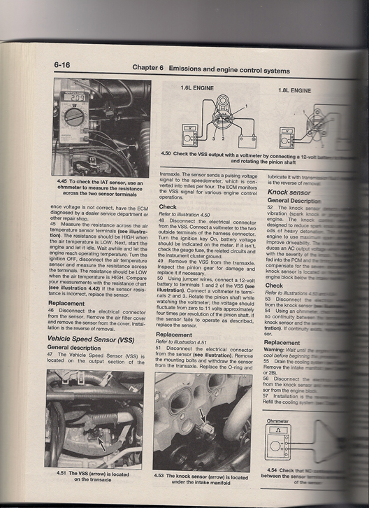
I wonder if the signal to the speedometer is electric. I do know when I remove the instrument cluster, I have to disconnect a lot of wires. Don't know if any of those is a square wave speed signal.
Quote:
Originally Posted by Occasionally6
I haven't looked, but how does MPGuino measure the speed input for your car?
|
Is that a generic question? If it is, I don't know the answer.
__________________________________________________
A few more questions: - The Arduino boards have analog and digital input pins. Which is better and which should I use?
- For the accel. board, do I run 1 wire from each x,y,z sensor to 1 input on the Arduino, or does each sensor wire get its own input (1 for X to pin 1, 1 for Y to pin 2, 1 for Z to pin 3)?
- Are the pins' input and output combined into the same pin? If so, how does the Arduino know if it is an input or an output, or does it matter? Will that be something I design in the Sketch ("If this happens, then run signal through pin X")?
- Would a gyro help me in this endeavor at all? Gyro, or is it not necessary?
__________________
Don't forget to like our Facebook page!


Best EM Quotes:
Quote:
Originally Posted by aerohead
It has been said, that if you peel the duct tape back on Earth's equator, you'll find that the two hemispheres are held together with J B Weld.
|
Quote:
Originally Posted by Dan9
subscribed with a soda.
|
Quote:
Originally Posted by aerohead
If you're burning,and someone throws gasoline on you,there will be a localized cooling effect, but you're still on fire.
|
Last edited by jeff88; 05-17-2013 at 10:06 PM..
|
|
|
|
|
05-19-2013, 02:04 AM
|
#37 (permalink)
|
|
Master EcoModder
Join Date: Apr 2013
Location: World
Posts: 385
Thanks: 82
Thanked 82 Times in 67 Posts
|
Quote:
Originally Posted by jeff88
So I can do a single 3-axis board with the VSS or 2 3-axis boards if I cannot get the VSS to work? If that is the case, I might just do 2 3-axis boards, so I don't have to mess with any vehicle parts directly.
|
That would be like using two measuring tapes; there's no need. A gyroscope (unless that's what you meant) would add additional data. That could work too/instead.
Quote:
|
Does this one from the parts list output in I2C or in voltages? I couldn't find out from the datasheet provided. 3-Axis Accelerometer
|
Says it's analog here: https://www.sparkfun.com/products/9652
Quote:
|
According to the datasheet for the Accel. 3.6V is the maximum voltage it will accept. So I guess when I run power to the Mega/UNO, I will run the wires from the battery through the diodes into the Vin header. Then I will run a wire from the 3.3V header to the Accel. Does that sound right?
|
Yep.
Quote:
So from what I've read, the 1N4004 will have a voltage drop of about .7V. Is that correct? That means that with 6 diodes (wired in series?), the voltage will drop from battery voltage from 12.6 (assuming fully charged) down to 8.4. That is in the operating range specified, but is that too many diodes? Maybe if I use 4 diodes to get me under 10V, that might be better?
I'd rather put in a few diodes, so I don't accidentally overload the circuits... cheap insurance.
|
There are a number of ways to get power to the Arduino. They can also be powered via the USB connector, indeed will be while programming. Another suggestion to consider is gutting or using intact a cigarette lighter/accessory socket to USB socket adaptor.
When calculating the "battery" voltage, consider that the alternator will be charging at something more like 14V with the engine running. It would be sensible to check what it is.
Quote:
|
Wouldn't it be easiest to have the accel. just be in the correct position, so I don't have to do any other fancy work in the Sketch?
|
It would make the sketch simpler. It may be difficult to achieve physically.
Quote:
|
BTW, do I have to mount the board horizontally, or can I mount it vertically?
|
You can mount it vertically. That just means that what is nominally the z axis becomes the x or y axis. You just relabel the variables in the sketch to suit.
Quote:
|
According to my Haynes manual, "The sensor sends a pulsing voltage signal to the speedometer, which is converted into MPH." Does that help determine the signal output? It looks like there are three wires in the VSS output.
|
Perfect. It's uses a Hall sensor. It should be 50% duty cycle. That means it will be at 0V for the same angle of rotation as it is at 11V for. With the DMM you can easily check that. With 4 pulses per pinion rotation you should see 11V for 45 degrees of pinion rotation (= driveshaft rotation if they are both rotating together), then 0V for the next 45 degrees and the pattern repeat for the next 270 degrees.
You will tap into the "11V" signal wire. You can do that at the VSS or, more easily, at the ECU (especially if the ECU is in the cabin). Easiest is simply to splice into the signal wire but I don't like cutting into the harness.
When doing things like this I will make a patch harness. Find a wreck (junkyard) and cut off the terminal connector of the equivalent ECU or VSS harness with ~6-8" of the wire still attached.
Unpin the VSS ECU wire or use the VSS connector intact and replace it with the salvaged wire + pin socket or connector. (Be careful not to damage the terminal if unpinning - practice on the wreck).
Solder a pin (same diameter as that which is used on the ECU) or terminals (for connection at the VSS) to the 6-8" of wire (cut it shorter to suit) and attach the vehicle terminal or connector to that. Use heat shrink to protect the terminals against a short circuit.
You can then splice into the new wire without damaging the car wires and return the wiring to stock when you remove the accessory.
You will need to modify the signal on the splice before feeding it into the Arduino. It needs to be between 3V and 5V, not exceed the current limit for the Arduino pin and not pull the signal down so far it affects the VSS input to the ECU.
The way to do it is to put a voltage divider in the splice wire, which is connected to earth. The signal to the Arduino is taken from between the two resistors. The ratio of each resistor to the total resistance is such that the voltage drops give 5V at the point between the two resistors.
The total resistance should be as high as you can use and still get the Arduino to detect the speed input. Total resistance too low will pull the VSS signal to the ECU down. I would start with 10M Ohm and 8.2M Ohm 0.5W resistors (the closest that you can buy to the 8 Ohm a simple V=IR calculation would suggest) and go progressively lower if the Arduino doesn't work with that.
Don't go below 600 Ohm between the VSS signal wire and the Arduino (that will limit the current into the Arduino to < 10mA). Also check that the VSS signal to the ECU is still ~11V. Also check that the VSS signal voltage is actually 11V with the engine running (i.e. with the alternator supplying ~14V). If it goes higher with the engine running you will need a different ratio in the voltage divider to get the 5V.
I would build that circuit on a piece of veroboard (or similar) and put it in a potting box.
Here for reference:
Arduino - PulseIn
Arduino - Constants
Voltage divider - Wikipedia, the free encyclopedia
Quote:
|
Is that a generic question? If it is, I don't know the answer.
|
Just that someone else using an MPGuino in the same model will have solved the problem before.
__________________________________________________
Quote:
A few more questions:
The Arduino boards have analog and digital input pins. Which is better and which should I use? For the accel. board, do I run 1 wire from each x,y,z sensor to 1 input on the Arduino, or does each sensor wire get its own input (1 for X to pin 1, 1 for Y to pin 2, 1 for Z to pin 3)?
|
Each output - x, y and z - from the analog (i.e. not I2C) 3-axis board needs a separate analog pin. You might want one more of those reserved if you anticipate multiple switch inputs. You're going to run out of pins if you want to use gyro and linear accel. with analog inputs, and want to use a voltage divider on an analog pin for multiple switch inputs as well. You can still use the other pins as digital inputs for switches. You do have 6 pins already used by the LCD module.
Quote:
|
Are the pins' input and output combined into the same pin? If so, how does the Arduino know if it is an input or an output, or does it matter? Will that be something I design in the Sketch ("If this happens, then run signal through pin X")?
|
analogRead() is implicitly an input command.
Quote:
|
Would a gyro help me in this endeavor at all? Gyro, or is it not necessary?[/LIST]
|
You might be able to use a gyro to "dead reckon" the angle i.e. integrate angular acceleration (as for the linear accelerations) to get the total angle moved from a reference point. The integration in Arduino can't be a perfect sum of the accelerations so you would need to reset periodically back to a known starting angle avoid a creeping error.
You might use a situation where there is no change in any of the accelerations for a period of time, like 5 seconds, and/or the vector sum is equal to 1g to indicate the car is stopped. Then use the fact that the linear acceleration will only be that due to gravity when at rest. If you're on a slope in that situation you would use trig. to determine the angles. |
|
|
|
|
05-21-2013, 09:44 PM
|
#38 (permalink)
|
|
Lots of Questions
Join Date: Jan 2013
Location: San Jose
Posts: 665
Thanks: 343
Thanked 101 Times in 79 Posts
|
I decided to take a few days to think about this, sleep on it, research a little more and decide what I want to do. I am definitely behind as I will have to learn on the fly how to set everything up as my Arduino knowledge is nothing and my car knowledge is minimal at best. That just means I will continue to have lots of questions throughout this process.
Quote:
Originally Posted by Occasionally6
That would be like using two measuring tapes; there's no need. A gyroscope (unless that's what you meant) would add additional data. That could work too/instead.
|
But shouldn't we measure twice and cut once?  JK, that makes sense. From what I have read, gyros tend to be highly accurate, but drift and accelerometers tend to be less accurate, but don't drift, is that right? So for the best accuracy, I should have both and in the Sketch write in the equation to use both. Would something like this work? It has a +/-2g accel. Accelerometer/Gyro I can't seem to find one built into one module with a +/-1.5g accel. I'm not sure what to look for in a gyro. I can do two separate shields, but 1 would be simpler and cleaner.
Quote:
Originally Posted by Occasionally6
When doing things like this I will make a patch harness. Find a wreck (junkyard) and cut off the terminal connector of the equivalent ECU or VSS harness with ~6-8" of the wire still attached.
Unpin the VSS ECU wire or use the VSS connector intact and replace it with the salvaged wire + pin socket or connector. (Be careful not to damage the terminal if unpinning - practice on the wreck).
Solder a pin (same diameter as that which is used on the ECU) or terminals (for connection at the VSS) to the 6-8" of wire (cut it shorter to suit) and attach the vehicle terminal or connector to that. Use heat shrink to protect the terminals against a short circuit.
You can then splice into the new wire without damaging the car wires and return the wiring to stock when you remove the accessory.
|
I get what you're saying about the patch harness and I like that idea so I don't need to make any permanent cuts. My only problem is I'm a little confused about the execution of it. How do I attach the patch harness to the OEM harness? I'm not getting how to do that without cutting in or doing anything permanent to the OEM harness.
Quote:
Originally Posted by Occasionally6
You will need to modify the signal on the splice before feeding it into the Arduino. It needs to be between 3V and 5V, not exceed the current limit for the Arduino pin and not pull the signal down so far it affects the VSS input to the ECU.
The way to do it is to put a voltage divider in the splice wire, which is connected to earth. The signal to the Arduino is taken from between the two resistors. The ratio of each resistor to the total resistance is such that the voltage drops give 5V at the point between the two resistors.
The total resistance should be as high as you can use and still get the Arduino to detect the speed input. Total resistance too low will pull the VSS signal to the ECU down. I would start with 10M Ohm and 8.2M Ohm 0.5W resistors (the closest that you can buy to the 8 Ohm a simple V=IR calculation would suggest) and go progressively lower if the Arduino doesn't work with that.
Don't go below 600 Ohm between the VSS signal wire and the Arduino (that will limit the current into the Arduino to < 10mA). Also check that the VSS signal to the ECU is still ~11V. Also check that the VSS signal voltage is actually 11V with the engine running (i.e. with the alternator supplying ~14V). If it goes higher with the engine running you will need a different ratio in the voltage divider to get the 5V.
I would build that circuit on a piece of veroboard (or similar) and put it in a potting box.
|
Just wanted to make sure I understand how the voltage divider works. I did a little mock up, using the Wikipedia pic, is this right?
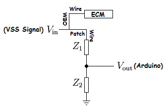
So the difference between the two resistors is what gives the Vout, so the size of the resistor doesn't matter as long as there is a difference (the size matters for current, but not for voltage)?
Can you explain how the V=IR works out to 8M ohms please? So if 5volts and 8.2Mohm, an online calculator says that would mean amps is 6.09e-7. Is that right? I need to have it less than 40milliamps (I think), but that is way less according to the calculator.
Is this what you are talking about? 8.2M ohm resistor What does the % mean?
Quote:
Originally Posted by Occasionally6
Each output - x, y and z - from the analog (i.e. not I2C) 3-axis board needs a separate analog pin. You might want one more of those reserved if you anticipate multiple switch inputs. You're going to run out of pins if you want to use gyro and linear accel. with analog inputs, and want to use a voltage divider on an analog pin for multiple switch inputs as well. You can still use the other pins as digital inputs for switches. You do have 6 pins already used by the LCD module.
|
It looks like I will have to get the MEGA board. The UNO only has 6 analog inputs, which sounds like won't be enough. 3 for the accel., 3 for the gyro, 1 for the VSS, and any others I might need. If I get the MEGA, I will know I have enough pins to do what I want and have extra for any other projects I want to do. I put the display I would like to use in the parts list. Common Cathode LED There is also a common anode display (in the parts list), but I'm not sure what I need (if it will work at all). It says it uses 10 pins, but I wasn't sure if I can use that for an Arduino setup. If it will work with the Arduino, I assume it uses digital pins.
Quote:
Originally Posted by Occasionally6
You might be able to use a gyro to "dead reckon" the angle i.e. integrate angular acceleration (as for the linear accelerations) to get the total angle moved from a reference point. The integration in Arduino can't be a perfect sum of the accelerations so you would need to reset periodically back to a known starting angle avoid a creeping error.
|
I found a forum where somebody has figured out how to setup a gyro and accel. and eliminate the creep. Creep elimination Would this help so I don't have to reset to the starting angle?
Quote:
Originally Posted by Occasionally6
You might use a situation where there is no change in any of the accelerations for a period of time, like 5 seconds, and/or the vector sum is equal to 1g to indicate the car is stopped. Then use the fact that the linear acceleration will only be that due to gravity when at rest. If you're on a slope in that situation you would use trig. to determine the angles.
|
Would this be done to eliminate creep? Would this be necessary with the Kalman filter. Would there be a way to set it up so that after so at a set time (using the time code: time), say 5:00AM, the arduino will reset itself? I don't know if there is a way for the Arduino to automatically come on and then shutoff after re-calibration.The idea would be that when I am at home (parked in the same spot as always), it will reset and the angle of the car would then be implied. Again though, would this be necessary with the filter?
__________________
Don't forget to like our Facebook page!
Best EM Quotes:
Quote:
Originally Posted by aerohead
It has been said, that if you peel the duct tape back on Earth's equator, you'll find that the two hemispheres are held together with J B Weld.
|
Quote:
Originally Posted by Dan9
subscribed with a soda.
|
Quote:
Originally Posted by aerohead
If you're burning,and someone throws gasoline on you,there will be a localized cooling effect, but you're still on fire.
|
|
|
|
|
|
05-22-2013, 03:50 AM
|
#39 (permalink)
|
|
Master EcoModder
Join Date: Apr 2013
Location: World
Posts: 385
Thanks: 82
Thanked 82 Times in 67 Posts
|
Quote:
Originally Posted by jeff88
I decided to take a few days to think about this, sleep on it, research a little more and decide what I want to do.
|
That's what I do too.
Quote:
|
From what I have read, gyros tend to be highly accurate, but drift and accelerometers tend to be less accurate, but don't drift, is that right?
|
You've got me on that. It may depend upon the context in which they are being used though. A low speed robot can be easily referenced to gravitational acceleration to correct drift.
Quote:
|
So for the best accuracy, I should have both and in the Sketch write in the equation to use both.
|
It's just that there's going to be more than one way to do what you want. VSS input and calc. slope from the separated x-axis accel., or use the gyro to dead reckon the angles from a known starting point (or points).
Quote:
|
I can do two separate shields, but 1 would be simpler and cleaner.
|
I think there may be some extra error with using separate IC's for accel. and gyro. There's some comment on that in one or more of the Sparkfun descriptions for their 6-axis boards.
Quote:
|
I get what you're saying about the patch harness and I like that idea so I don't need to make any permanent cuts. My only problem is I'm a little confused about the execution of it. How do I attach the patch harness to the OEM harness? I'm not getting how to do that without cutting in or doing anything permanent to the OEM harness.
|
See thumbnail.
Quote:
|
Can you explain how the V=IR works out to 8M ohms please? So if 5volts and 8.2Mohm, an online calculator says that would mean amps is 6.09e-7. Is that right? I need to have it less than 40milliamps (I think), but that is way less according to the calculator.
|
V=IR is the basis for the proof. 10MOhm is my ballpark safe minimum resistance to avoid altering the ECM signals. It's arbitrary but based on the spec. that many vehicle manufacturers have for DMM's being used for diagnosis; >10M Ohm impedance.
The current you pull through the Arduino plus that through R2 also goes through the VSS, in addition to what is already being drawn by the ECM. Keeping the extra to a minimum minimises the possibility of damaging the VSS and avoids altering the signal that the ECM gets. I doubt it's going to be a problem though.
You might like to measure the current being drawn by the VSS (with the signal high i.e. 11V). That will tell you proportionally how much extra you are adding to it through the voltage divider.
Vout = {R2/(R1 + R2)} x Vin
5V = {R2/(10M + R2)} x 11V
Solving for R2 gives ~8M
Those resistances may be too high to get the Arduino to register the signal and you will have to reduce them. I don't know the lowest possible current it will detect on a pin. There's got to be spec. somewhere though.
Quote:
|
Is this what you are talking about? What does the % mean?
|
Yep. That's an expensive resistor though (I know it's the price for a pack).
"2%" is the tolerance. eg. a nominally 100 Ohm resistor could be between 98 and 102 Ohms.
Quote:
|
It looks like I will have to get the MEGA board. The UNO only has 6 analog inputs, which sounds like won't be enough. 3 for the accel., 3 for the gyro, 1 for the VSS, and any others I might need.
|
The VSS can be a digital only pin i.e. any Arduino input/output pin, but otherwise, for analog accel and gyro input, yes.
Quote:
|
I put the display I would like to use in the parts list. There is also a common anode display (in the parts list), but I'm not sure what I need (if it will work at all). It says it uses 10 pins, but I wasn't sure if I can use that for an Arduino setup. If it will work with the Arduino, I assume it uses digital pins.
|
Yes, you can use that. As it stands, it will require 9 or 10 pins on the Arduino, yes, configured as digital pins. You use 7 pins to drive each of the segments, plus 2 to switch between which of the two digits is on. (Very fast; like a movie film, the human eye doesn't register that the displays are being switched on and off.) Use transistors between the Arduino and each common pin.
You don't necessarily need to use an Arduino pin for the decimal point(s). If that doesn't move; wire it to ground (common anode) or power (common cathode) through a current limiting resistor. The 7 led segments also each need (just 7, not 2 x 7; only 1 digit is on at a time) resistors in between them and the Arduino pin.
A way to reduce the number of pins from 7 to 4 is to use the BCD to 7-segment IC (4511) that I mentioned earlier. That converts a 4 bit binary number to the 7-segment output. You use 4 of the Arduino pins to describe the binary. eg. 8 dec is 1000 bin; one of the Arduino pins is switched high, the rest low (in the sketch), and that is fed into 4 of the 4511 pins. The 4511 IC then switches (all) the 7 segment outputs on to display the 8. With a common anode 7 segment you might need transistors to reverse the 4511 output from supply to ground. (I'd have to look at a data sheet to check how it works. I am pretty sure that it supplies current.)
If you are going to use that, you will need a board to make the circuit on i.e. a shield.
Are you sure you want to use that though? The LCD display module is easier and allows more display options (any ASCII character). The only downside is it costs more.
Quote:
|
I found a forum where somebody has figured out how to setup a gyro and accel. and eliminate the creep. Would this help so I don't have to reset to the starting angle?
|
Thanks for the link. I will have to read that more thoroughly than I can atm (that guy is way ahead of where I am) to understand what he did but in general, I think there's a lot there that could be adapted. The principle is the same. (I have a few sketches that I got to via links from there. Some of them look like they will be useful.)
Quote:
|
Would this be done to eliminate creep? Would this be necessary with the Kalman filter.
|
The Kalman filter is new to me. I think any filter can only reduce the error, not eliminate it. He did use it on a robot. There will be some differences with that and a vehicle.
Quote:
|
Would there be a way to set it up so that after so at a set time (using the time code: time), say 5:00AM, the arduino will reset itself? I don't know if there is a way for the Arduino to automatically come on and then shutoff after re-calibration.The idea would be that when I am at home (parked in the same spot as always), it will reset and the angle of the car would then be implied. Again though, would this be necessary with the filter?
|
You will have to reset at some point; there will always be some error. The time idea is interesting. You may have a better idea if it is workable or not with more accurate knowledge of how much error there is. I suspect that a typical length trip is too long not to require a baseline reset several times throughout it. That shouldn't be a problem if you stop at least a few times or possibly travel at a steady speed for a few seconds at a time.
Last edited by Occasionally6; 05-22-2013 at 04:25 AM..
Reason: power, ground and common cathode and anode relations transposed
|
|
|
|
|
The Following User Says Thank You to Occasionally6 For This Useful Post:
|
|
|
05-22-2013, 04:05 AM
|
#40 (permalink)
|
|
Master EcoModder
Join Date: Apr 2013
Location: World
Posts: 385
Thanks: 82
Thanked 82 Times in 67 Posts
|
This what I have used. Items in brackets I could have omitted. The exact parts list will depend upon how you want to arrange the parts.
Gduino Parts List
Essential
Arduino
Hitachi HD 44780 compatible display module
+/-1.5g 3-axis analog output accelerometer board
Other parts
16 wire ribbon cable
prototype shield board
(2 x 100nF capacitors)
(PCB mounted momentary tactile switch)
(LED)
(1k 1/2W resistor)
4 core twisted pair, solid core telephone cable (With the outer insulation stripped off this gives 8 color insulated solid core wires for the circuit board connections.)
(6.0mm (1/4" ) heatshrink)
14 pin Oupiin circuit baord to ribbon cable connector
2 of (8 x 1) pin and 2 of (6 x 1) pin header pins
Consumables
resin cored solder
(solder wick/braid)
Non-Consumables
USB a - USB b cable
Tools
Soldering iron
(DMM)
Wet sponge or cloth (to clean the soldering iron)
blade (craft knife or box cutter)
wire cutter
wire stripper
(tweezers)
I have a quick and dirty sketch running that displays the x, y and z g readings in g. The $100 (actually just under $90) pendulum is up and running.
|
|
|
|
|


