Go Back   EcoModder Forum > EcoModding > Fossil Fuel Free
Register Now
 Register Now
 

Reply  Post New Thread
 
Submit Tools LinkBack Thread Tools
Old 10-27-2014, 10:13 AM   #31 (permalink)
EcoModding Apprentice
 
Join Date: Oct 2014
Location: Netherlands, Europe
Posts: 118
Thanks: 2
Thanked 27 Times in 20 Posts
Quote:
Originally Posted by z_power View Post
We (Poland) still have quite liberal regulations regarding technical approval but after joining EU there's drift in the same direction
How are the rules there regarding EV conversion? Here in Holland we can't have a motor or controller be DIY or from something else, it has to have a certificate for use in a road vehicle, and to get one, costs a ton of money. Strangely enough, importing cars that have been approved in other EU states with much less strict rules is totally okay, so if I can find one that lets me use an old forklift motor or an industrial AC motor and a self-designed controller, then I can afford an EV conversion too. (Not going to put €20k of motor/controller in a €1k car..)


Last edited by AlexanderB; 10-27-2014 at 10:45 AM..
  Reply With Quote
Alt Today
Popular topics

Other popular topics in this forum...

   
Old 10-27-2014, 10:22 AM   #32 (permalink)
Administrator
 
Daox's Avatar
 
Join Date: Dec 2007
Location: Germantown, WI
Posts: 11,203

CM400E - '81 Honda CM400E
90 day: 51.49 mpg (US)

Daox's Grey Prius - '04 Toyota Prius
Team Toyota
90 day: 49.53 mpg (US)

Daox's Insight - '00 Honda Insight
90 day: 64.33 mpg (US)

Swarthy - '14 Mitsubishi Mirage DE
Mitsubishi
90 day: 56.69 mpg (US)

Daox's Volt - '13 Chevrolet Volt
Thanks: 2,501
Thanked 2,586 Times in 1,554 Posts
De-iced, nice!
__________________
Current project: A better alternator delete
  Reply With Quote
Old 10-28-2014, 05:41 PM   #33 (permalink)
EcoModding Lurker
 
Join Date: Dec 2011
Location: Poland
Posts: 66
Thanks: 12
Thanked 27 Times in 22 Posts
Quote:
Originally Posted by AlexanderB View Post
How are the rules there regarding EV conversion?
Well, the rules are slowly getting tighter but as usual in our part of the world execution of these rules is... not so tight, to say. While registration of scratch built cars became painful and expensive, conversions of already registered ones are not that hard to legalize. I'd say ~500€ is upper limit on expenses (legal fees, expert opinions and tech examinations).

I still didn't legalize my conversion because it's not clean enough ("messy" contactor box, heater noot installed etc.) so no 1st hand experience, but I already did research at local registration office and at examination stations. Will let you know when I pass it.
  Reply With Quote
Old 10-28-2014, 06:24 PM   #34 (permalink)
EcoModding Apprentice
 
Join Date: Oct 2014
Location: Netherlands, Europe
Posts: 118
Thanks: 2
Thanked 27 Times in 20 Posts
I can imagine, you only want to go once and get it right, and not have them say "no" and take your plates away, making further test driving impossible.

The only reason I'd do it as quickly as possible, is because we pay a lot of tax each month, and electric cars are (for now) not taxed. A pretty good saving, that makes the conversion a little more wallet-friendly to run.

Please. I'm quite curious how it will go.
  Reply With Quote
Old 11-30-2014, 08:49 PM   #35 (permalink)
Dreamer
 
Join Date: Nov 2013
Location: Australia
Posts: 350
Thanks: 95
Thanked 214 Times in 151 Posts
Some more progress.
I visited a local wreckers and found a electric power steering pump.
Took a little while to extract it from the car, i have no idea why manufacturers put things where they do. Eventually it was extracted and the cost was $50.
I also found a vacuum reservoir to complete the brakes which cost me $10.
Also located a few items for my ICE vehicles.
So quite a productive rummage at the wreckers.

I welded up a bracket to mount the P/S pump using some existing mount points in the engine bay. Next i will have to get the hydraulic hoses joined up. I will get the high pressure line made up professionally, way too many PSI for my skills.

The A/C hose looks close but it will move once the A/C compressor is mounted to the motor. I may need to make alterations to the mounting bracket but i will wait and see where the hose ends up.
At the moment there is about an inch of clearance between the top of cap on the P/S module and the underside of the bonnet. So there is some room to move vertically but not much. The module could be moved horizontally further back towards the battery. Where it is at the moment was the easiest spot given the existing mount points available. If it needs some refining later then that is ok.


I welded up a bracket to mount the electric vacuum pump.
I just combined an existing bracket for a part that is no longer required with the bracket that came with the vacuum pump.
It will live under the wheel arch out of the way.
The vacuum reservoir will be mounted under there too.

As i look at this bracket now i am wondering if i should have added some diagonal bracing to help support the pump. The spot welded joint may not hold up long term. I will have to ponder that some more.


My father-in-law and i thrashed out some more details on the hub and adaptor plate setup. The plan is to use a taperloc in the hub. This should give the hub a nice snug fit. Combined with the keyway there shouldn't be any movement.

I ordered the rest of my cells for the traction pack. I already had 4 cells that i was using to test the BMS modules on as i built them. Now i have ordered an additional 44 cells to make up the 48 cell 156 volt traction pack. This was the most expensive purchase of the entire build. About a quarter of the total build cost is the batteries.

I have started welding up the battery rack for the traction pack. Looks like it will fit neatly.
Still lots more welding to be done on it before it is complete.
The battery rack It is going to be a self contained battery module with the main and precharge contactors integrated into it. So when the contactors are de-energised the high voltage is only inside the pack. It will be attached by several easily removed bolts so that the entire pack can be easily removed for maintenance and inspections.
It needs easy to remove as it will be mounted under the car in the void left by the petrol tank which would be too awkward to work on without removing the pack. Well that's the plan anyway.
  Reply With Quote
The Following User Says Thank You to Astro For This Useful Post:
MPaulHolmes (12-03-2014)
Old 12-03-2014, 09:07 AM   #36 (permalink)
PaulH
 
MPaulHolmes's Avatar
 
Join Date: Feb 2008
Location: Maricopa, AZ (sort of. Actually outside of town)
Posts: 3,832

Michael's Electric Beetle - '71 Volkswagen Superbeetle 500000
Thanks: 1,368
Thanked 1,202 Times in 765 Posts
How did I miss your build thread!? Thank you for showing your progress. That was really fun to read.
__________________
kits and boards
  Reply With Quote
The Following User Says Thank You to MPaulHolmes For This Useful Post:
Astro (12-03-2014)
Old 12-27-2014, 12:58 AM   #37 (permalink)
Dreamer
 
Join Date: Nov 2013
Location: Australia
Posts: 350
Thanks: 95
Thanked 214 Times in 151 Posts
Well, the lack of diagonal bracing did wear away at me.

So i added in some bracing and while i was at it i re-did the power steering pump mounting bracket as well.

Re-work is so much fun.

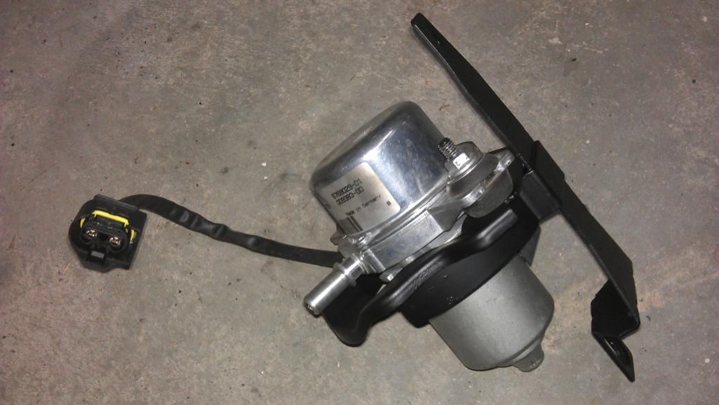
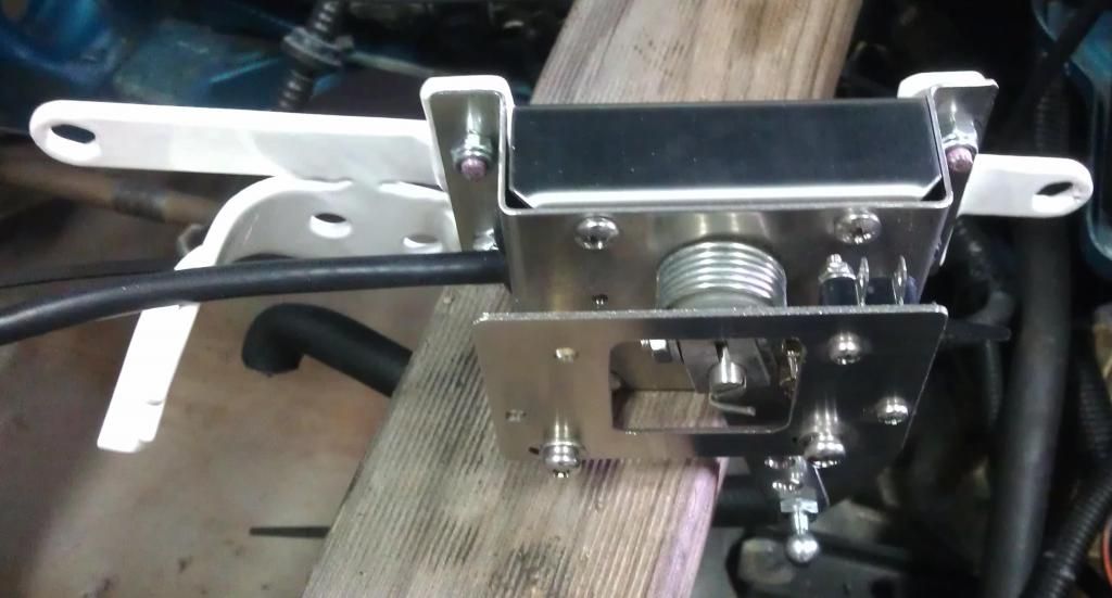
At least now i feel the brackets are all they should be. Below are the vacuum pump, throttle and power steering brackets.


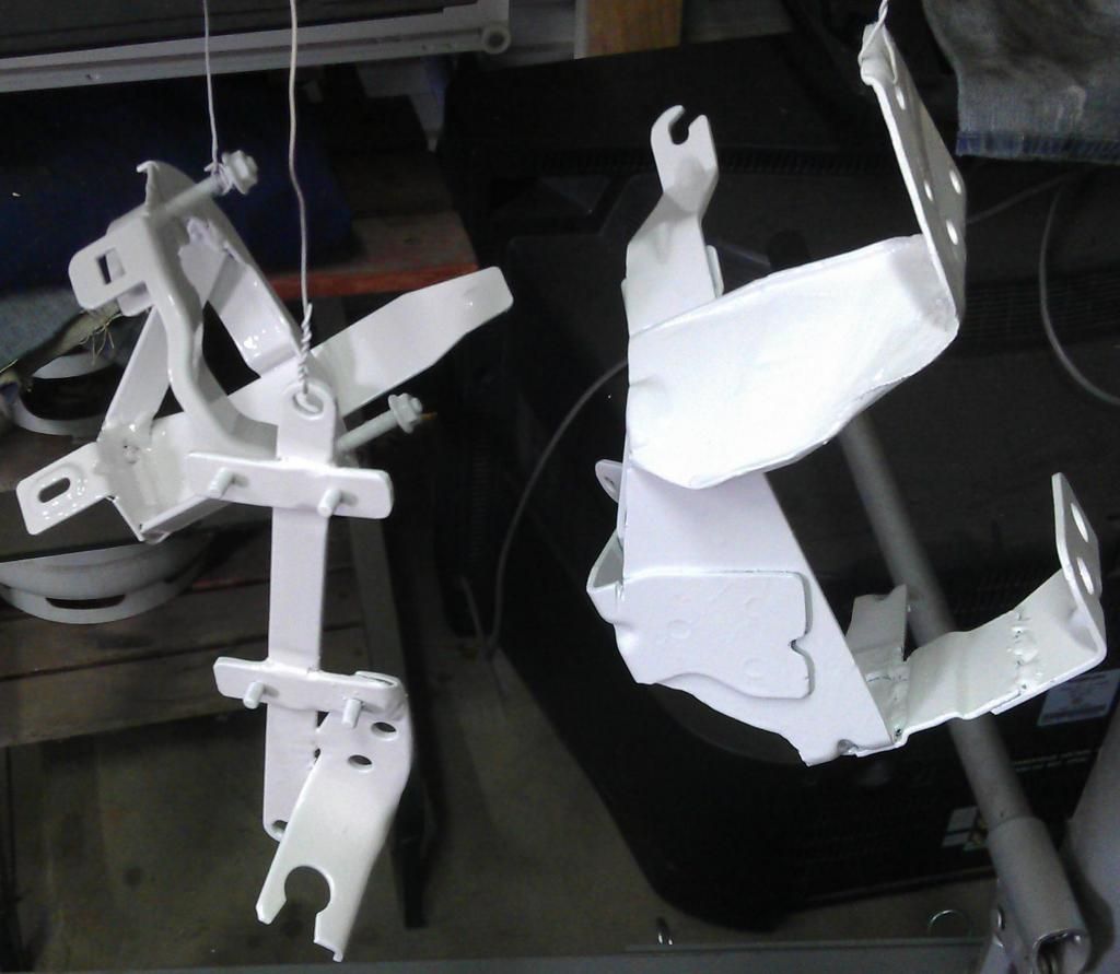
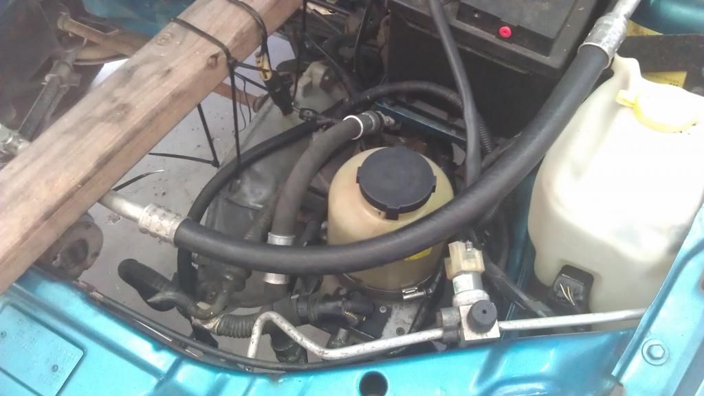
The Power steering bracket was modified to allow the pump to sit further back in the engine bay and slightly higher, giving more clearance for the A/C hose in front of it and the clutch cable below it.


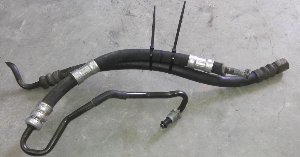
I cable tied both sections of power steering hose together. The section that came with the Astra's power steering pump and the section from the Barina's steering rack.
I marked across both so i would know how long the joined hose will need to be.
I will take it round to the hydraulic hose guys to make a single hose out of it.
Way too many PSI (1200 to 1500) for me to consider doing myself.
Not sure if they will join the hose sections or just replace the entire hose part.
The hose sections my be dissimilar and incompatible.


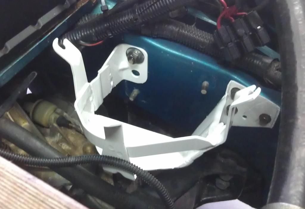
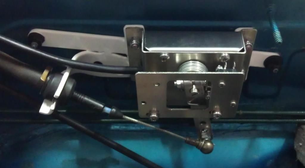
The hall effect throttle assembly was mounted to the bracket.

I went with the hall effect type of throttle as it will be immune from wear that can cause noisy signals when using a resistive type. Just make sure whatever controller you use it supports hall effect throttles.
Paul's AC controller supports hall effect throttles so that will be perfect.

Then the bracket was mounted to the firewall and the throttle cable attached. It all fitted first go. Didn't need to adjust anything. Had to happen eventually.


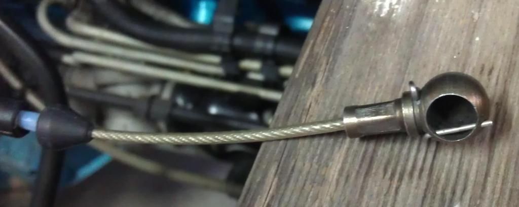
The Barina throttle connector is a ball and socket type. I found a suitable ball on ebay that fitted perfectly.
Throttle Linkage Ball 5 16" OD 8mm 43706 | eBay


From there i made a start on building a replacement for the cabin heater core.
Stripped down a ceramic heater for it's element and holder.
Then i fabricated a metal box to the same dimensions as the heater core. (It will look better once painted up )
I know, nobody will ever see it again once it is installed but i will see it every time i look at the car. A bit obsessive maybe but i need to have something to blame for how long the build is taking.


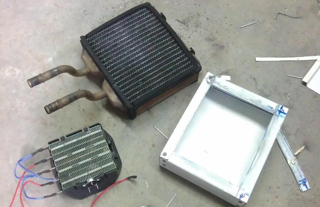
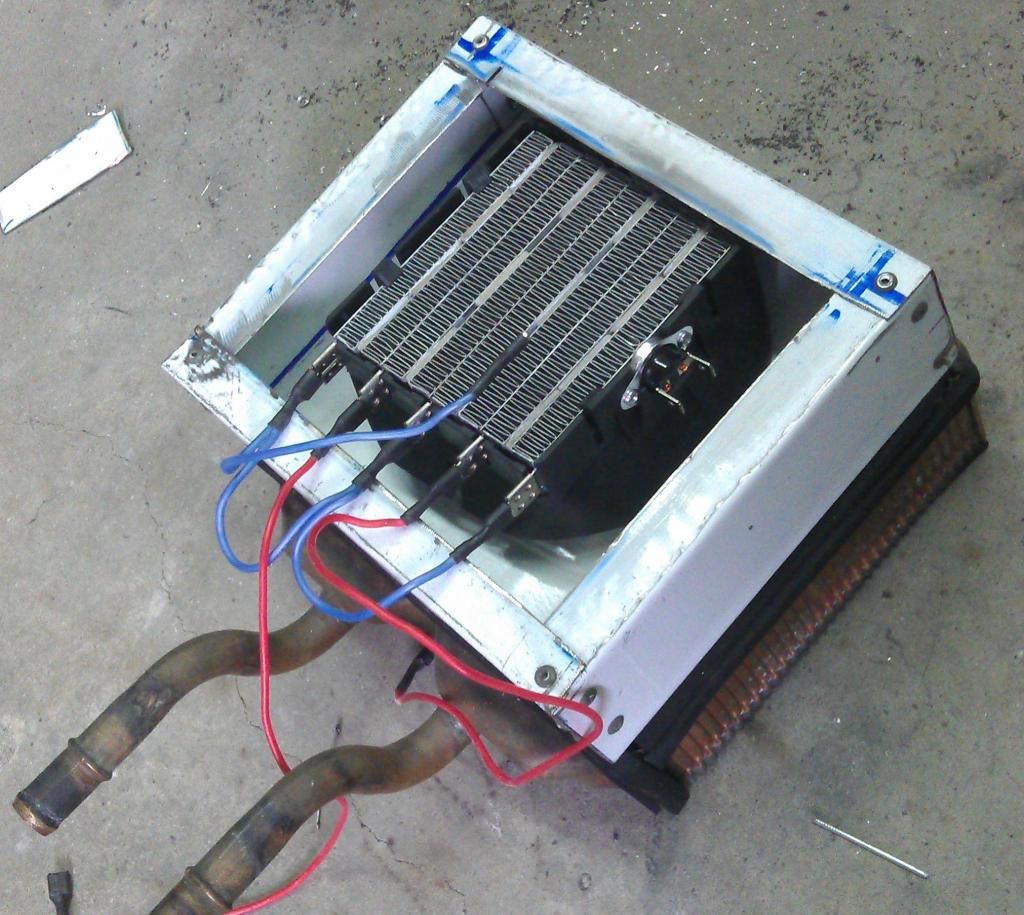
Here is a roughly how it will come together. I still need to cut the hole below the element and then glue and rivet the the element holder in.


I tested the element to see if it will work ok with DC rather than AC. 96v was all the charged 12v batteries i had handy.
Oh and by the way, yes, 96v DC does give a bit of a tingle when you decide to include your body in the circuit.

I had read that the ceramic element is self limiting. As the temperature increases the current reduces.
Sounded a little too good to be true but when i tested it that was exactly what happened. Initially current increased as the elements temperature increased but then as the element got to about 180C the current started reducing. The current continued to reduce until an equilibrium was reached and the temperature stopped at around 205C.
This was with no air flow through the element.
Blowing a small amount of air through the element caused the current to increase slightly and the temperature to remain at 205C.

The element has a thermal switch mounted to the side of it. This cuts the power when the element reaches about 180C and turns it back on when the temperature drops below 140C.
Not sure if i should run the element at its equilibrium temperature of 205C or let the thermal switch cycle the element on and off.
Not sure which is best for long term reliability. Is running the element at 205C going to shorten its life or is the thermal switch going to fail as it is now switching 156v DC rather than 240v AC?

Last edited by Astro; 01-16-2015 at 06:02 PM.. Reason: Added that the throttle is hall effect type
  Reply With Quote
Old 12-27-2014, 07:50 PM   #38 (permalink)
It's all about Diesel
 
cRiPpLe_rOoStEr's Avatar
 
Join Date: Oct 2012
Location: Porto Alegre, Rio Grande do Sul, Brazil
Posts: 12,571
Thanks: 0
Thanked 1,627 Times in 1,452 Posts
Quote:
Originally Posted by Astro View Post
The element has a thermal switch mounted to the side of it. This cuts the power when the element reaches about 180C and turns it back on when the temperature drops below 140C.
Not sure if i should run the element at its equilibrium temperature of 205C or let the thermal switch cycle the element on and off.
Not sure which is best for long term reliability. Is running the element at 205C going to shorten its life or is the thermal switch going to fail as it is now switching 156v DC rather than 240v AC?
I'd rather run it at the thermostatically-controlled temperatures, both for long-term reliability and to avoid fire risk to the car parts surrounding the ceramic element
  Reply With Quote
The Following User Says Thank You to cRiPpLe_rOoStEr For This Useful Post:
Astro (12-28-2014)
Old 12-28-2014, 03:37 AM   #39 (permalink)
Dreamer
 
Join Date: Nov 2013
Location: Australia
Posts: 350
Thanks: 95
Thanked 214 Times in 151 Posts
I think you are right.
I ordered a couple of extra thermo switches. One 130C and one 105C.
One of them should replicate more closely the temperature the original heater core generated.
  Reply With Quote
Old 12-28-2014, 04:04 AM   #40 (permalink)
It's all about Diesel
 
cRiPpLe_rOoStEr's Avatar
 
Join Date: Oct 2012
Location: Porto Alegre, Rio Grande do Sul, Brazil
Posts: 12,571
Thanks: 0
Thanked 1,627 Times in 1,452 Posts
You can also consider to add some thermal insulation behind the dash, and around this metallic case you're making for the ceramic heater, in order to keep the dash more protected from that heat blast. That could eventually also make the heat irradiation more efficiently-directed thru its original HVAC ducts.

  Reply With Quote
Reply  Post New Thread


Tags
barina


Powered by vBulletin® Version 3.8.11
Copyright ©2000 - 2024, vBulletin Solutions Inc.
Content Relevant URLs by vBSEO 3.5.2
All content copyright EcoModder.com