 01-18-2013, 04:29 PM
|
#11 (permalink)
|
|
Master EcoModder
Join Date: Aug 2011
Location: Warren, MI
Posts: 2,456
Thanks: 782
Thanked 668 Times in 410 Posts
|
Quote:
Originally Posted by ennored

If the Dryden van and all the boattails out there were right, surely the the boattails shown there hurting or barely improving the drag couldn't be right. What was wrong?
|
I'm not totally following that series of images either, but will say that when the top angle drops below 20 degrees (safe) to 24 degrees (one or two beyond the attached flow threshold, depending on who you ask) the drag goes up substantially. I think it's demonstrating the numbers game of rear-end angles...
__________________
He gave me a dollar. A blood-soaked dollar.
I cannot get the spot out but it's okay; It still works in the store
|
|
|

|
 Today Today
|
|
|
|
 Other popular topics in this forum...
|
|
|
|
|
01-18-2013, 05:09 PM
|
#12 (permalink)
|
|
Master EcoModder
Join Date: Jan 2008
Location: Sanger,Texas,U.S.A.
Posts: 15,879
Thanks: 23,955
Thanked 7,219 Times in 4,646 Posts
|
clock
Quote:
Originally Posted by ennored
First, let me say, my brain hurts! Lots of thinking going on lately.
I had read the entire thread mentioned above. Saw the images on page #25. I was having a little trouble with the second batch of images quoted above, the piggy bank looking box. If the Dryden van and all the boattails out there were right, surely the the boattails shown there hurting or barely improving the drag couldn't be right. What was wrong? I think it's in the last piggybank. the shaded area I assume is the sides being angled in, duh, addressing on the top wasn't doing too much by itself. Right?
And something else I have been playing with. The shape of the tail, that's where this thread kind of started. I'm still a bit stuck on the Dryden van, but I have also now read threads about Cinderella, and Tiger Woods. I'm an engineer, there must be a spreadsheet, right? There is:
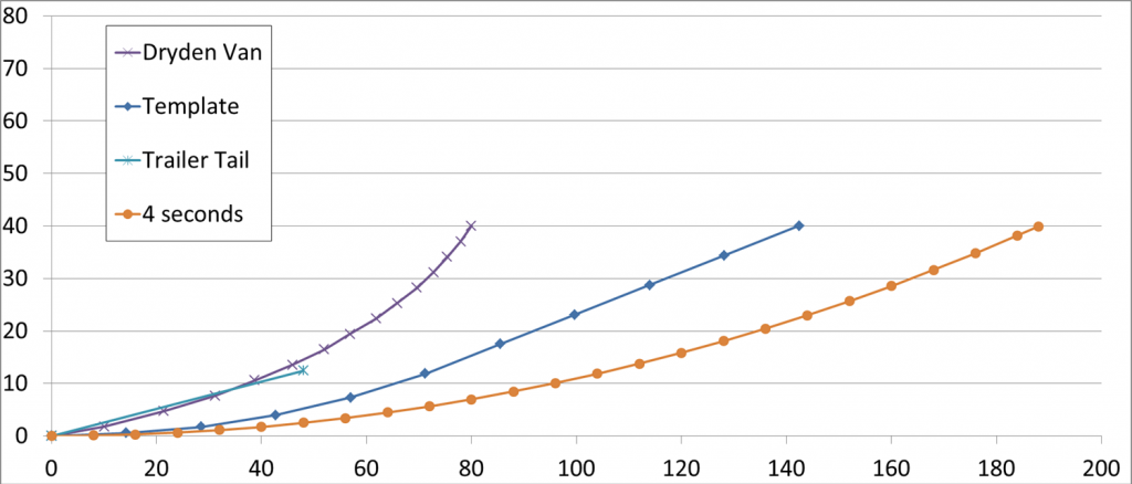
(X and Y scales are in inches, based on the Dryden van that was 80" wide.)
I was doing OK until the Cinderella threads. 4 seconds, 5 seconds, 22°, I'm still processing. A simple "4 second" tail is much longer than the template. Easy to make the following observations about end of the clockface tail:
3.66 seconds - 22°
4 seconds - 24°
5 seconds - 30°
I get that a simple clock doesn't a template make, but thought I'd be closer. A "5 second" clock starts to get close to the template, but has 30° of taper in it. It ain't so simple! But you all knew that. I guess my question is, just what clock is worthy of a basic template? One at something like 5.5 seconds, limited to 22° would be close to the template. I may narrow that down, but haven't seen it here, I must be off on an unreasonable path?
And back to my graph. Both the Dryden van, which was tuft tested, and the Trailer Tail, which was optimized for angle, are very close. They both have limited lengths (80" and 48"). Both seem to work very well. Just what is a good model for a practical tail? (Recall I'm thinking about large vehicles, 100" wide, so the template tail is like 178", not practical at all.) |
The analog clock face represents a 3-D sphere(dimpled golf ball if you will) moving from right to left with supercritical flow and turbulent boundary layer.
The forward stagnation point occurs at the 9:00 position,and the separation point occurs 115-degrees downstream,at 4-seconds after.
Flow separation always seems to occur at 4-seconds after,so the arc,from 12:00 high,to 4-seconds after,or 6:00 low,to 26-seconds before 6:00 will describe a curvilinear architecture which will support attached flow between these limits.
If you use a Rolex watch for the 'nose,' and Big Ben for the 'tail,' you get,roughly,a streamline body of revolution of 2.5:1 fineness ratio,with the 1/2 convex-hemispherical forebody,and bifurcated hyperboloid aft-body with completely attached flow for its entire length and Cd 0.04 in free flight.
It's not the best 'template,' but when all else failed it could function as such.
__________________
Photobucket album: http://s1271.photobucket.com/albums/jj622/aerohead2/
|
|
|
|
|
01-18-2013, 05:22 PM
|
#13 (permalink)
|
|
Master EcoModder
Join Date: Jan 2008
Location: Sanger,Texas,U.S.A.
Posts: 15,879
Thanks: 23,955
Thanked 7,219 Times in 4,646 Posts
|
'Practical'
Losses from 'practical-length' vehicles can be measured in the trillions of Dollars.
The 'Template' describes an architecture which can achieve low drag (which,by definition, begins at Cd o.25 and goes down from there),with potentials on the order of Cd 0.12.
Each individual must decide what they can live with.Historically,the difference in length left on the table can be measured in millions of lives lost.Wars have been fought over quantities of petroleum which routinely go up in invisible smoke from the bodies of motor vehicles each year.
__________________
Photobucket album: http://s1271.photobucket.com/albums/jj622/aerohead2/
|
|
|
|
|
01-18-2013, 07:16 PM
|
#14 (permalink)
|
|
EcoModding Lurker
Join Date: Jan 2013
Location: United States
Posts: 6
Thanks: 0
Thanked 2 Times in 2 Posts
|
Those diagrams are entirely fascinating, though somewhat counter-intuitive. Ive been researching aerodynamics for years, though mostly for car/racing purposes (gaining downforce while minimizing drag). Its great to know theres always more to learn on topics like these.
I find it a bit interesting we dont see any iterations of that bus that has the bottom taper up? On race cars that tapering from the bottom is a diffuser, it creates downforce, but also minimizes drag. Is the increased downforce, and thus increased tire friction, the reason these "tails" do not taper from the bottom as well? From my understanding, tapering on the top and the bottom would be the best way to minimize drag, at the cost of slightly increased downforce. Hypothetically you could taper it to the size of a pencil, then with an air jet shot through this convergence point, you effectively get an "infinitely long" tail, without the need for additional panels. This is because the air jet, which needs to be faster than the air travelling around it, acts as a place where the slower moving air can grab onto (instead of the side of your car). This same phenomena is seen in modern jet craft pulse detonation engines, it allows for drastically increased efficiency on these pulse engines.
I do know they do similar things on some semi trucks, or at least toyed with the idea; in which they would have fast moving air "curtains" expelled the rear of the truck. This would limit the turbulence behind the truck and minimize its drag. As I recall this system drastically helped decrease drag and increase mpg, but the cost was substantial.
edit: The main reason I guess we dont see that tapering from the bottom partly relates to why it works as a diffuser. On a flat bottomed car such as a dedicated race car, the rear tapers up before the end of the car. This causes the air before the taper to speed up to maintain constant flow, this affects the pressure under the car, essentially pulling the car down (downforce). However it does increase drag as stated prior, due to the air velocity being faster after the taper. The only thing I can think is that this increased air velocity would cause aggressive turbulence past the end of the car, potentially nullifying the beneficial effects? Can anyone shed some light onto this?
It looks like the second diagram does touch this topic, and Cd is decreased, but its not a common theme I have seen on this site. Is it something that is being overlooked, or something that is purposely being ignored because it's benefit is negligable (and really only applies to cars with flat undertrays) or because it is simply not achievable in most applications?
|
|
|
|
|
01-18-2013, 07:34 PM
|
#15 (permalink)
|
|
Master EcoModder
Join Date: Sep 2012
Location: Motor City
Posts: 272
Thanks: 0
Thanked 212 Times in 131 Posts
|
Quote:
Originally Posted by aerohead
The analog clock face represents a 3-D ... occurs 115-degrees downstream,at 4-seconds after....
|
The 115° point is 25° after the 90° top (or bottom). That's just past 4 seconds (4.17 actually). So the 4 second circle I made in my graph is close to that. Hmmmm.
I did a little more playing, the curve of the template follows almost exactly a 6 second circle until about halfway down the template. Given that a truncated boattail is nearly as effective as a full one, that critical part of the template is very closely approximated by a circle. It might be arguable that any boattail, no matter the length, should start with a circular form? I need to play with my graph and see how circular the Dryden tail is...
Last edited by ennored; 01-18-2013 at 07:40 PM..
|
|
|
|
|
01-19-2013, 03:24 PM
|
#16 (permalink)
|
|
Master EcoModder
Join Date: Jan 2008
Location: Sanger,Texas,U.S.A.
Posts: 15,879
Thanks: 23,955
Thanked 7,219 Times in 4,646 Posts
|
diffusers
Quote:
Originally Posted by b23
Those diagrams are entirely fascinating, though somewhat counter-intuitive. Ive been researching aerodynamics for years, though mostly for car/racing purposes (gaining downforce while minimizing drag). Its great to know theres always more to learn on topics like these.
I find it a bit interesting we dont see any iterations of that bus that has the bottom taper up? On race cars that tapering from the bottom is a diffuser, it creates downforce, but also minimizes drag. Is the increased downforce, and thus increased tire friction, the reason these "tails" do not taper from the bottom as well? From my understanding, tapering on the top and the bottom would be the best way to minimize drag, at the cost of slightly increased downforce. Hypothetically you could taper it to the size of a pencil, then with an air jet shot through this convergence point, you effectively get an "infinitely long" tail, without the need for additional panels. This is because the air jet, which needs to be faster than the air travelling around it, acts as a place where the slower moving air can grab onto (instead of the side of your car). This same phenomena is seen in modern jet craft pulse detonation engines, it allows for drastically increased efficiency on these pulse engines.
I do know they do similar things on some semi trucks, or at least toyed with the idea; in which they would have fast moving air "curtains" expelled the rear of the truck. This would limit the turbulence behind the truck and minimize its drag. As I recall this system drastically helped decrease drag and increase mpg, but the cost was substantial.
edit: The main reason I guess we dont see that tapering from the bottom partly relates to why it works as a diffuser. On a flat bottomed car such as a dedicated race car, the rear tapers up before the end of the car. This causes the air before the taper to speed up to maintain constant flow, this affects the pressure under the car, essentially pulling the car down (downforce). However it does increase drag as stated prior, due to the air velocity being faster after the taper. The only thing I can think is that this increased air velocity would cause aggressive turbulence past the end of the car, potentially nullifying the beneficial effects? Can anyone shed some light onto this?
It looks like the second diagram does touch this topic, and Cd is decreased, but its not a common theme I have seen on this site. Is it something that is being overlooked, or something that is purposely being ignored because it's benefit is negligable (and really only applies to cars with flat undertrays) or because it is simply not achievable in most applications?
|
Your point is a good one but I'd be reluctant to tell stories about what was going through the minds of the researchers when they did the testing.
Diffuser technology is well understood and there are no legal constraints for those of us who'd like to exploit it personally.
For commercial applications it is possible that someone holds a utility patent for the technology which is still in force,and nobody wants to pay them a royalty.Don't know.
__________________
Photobucket album: http://s1271.photobucket.com/albums/jj622/aerohead2/
|
|
|
|
|
01-19-2013, 03:38 PM
|
#17 (permalink)
|
|
Master EcoModder
Join Date: Jan 2008
Location: Sanger,Texas,U.S.A.
Posts: 15,879
Thanks: 23,955
Thanked 7,219 Times in 4,646 Posts
|
circular
Quote:
Originally Posted by ennored
The 115° point is 25° after the 90° top (or bottom). That's just past 4 seconds (4.17 actually). So the 4 second circle I made in my graph is close to that. Hmmmm.
I did a little more playing, the curve of the template follows almost exactly a 6 second circle until about halfway down the template. Given that a truncated boattail is nearly as effective as a full one, that critical part of the template is very closely approximated by a circle. It might be arguable that any boattail, no matter the length, should start with a circular form? I need to play with my graph and see how circular the Dryden tail is...
|
I played around with the 'Template' and found that its profile can be defined by degrees of arc of rotation of four different radii,which emanate from the same Y-ordinate on a Cartesian grid.
The original 'Template' contour mimics the aft-body of a streamline body of revolution of 2.5:1 fineness ratio which Hucho portrayed in one of his drag tables.
NACA (NASA) described these forms as hyperboloids.And there would be a formula for that particular contour.I don't have it.I just do graphical solutions based on the architecture.I believe that it is the reason aerodynamicists present these forms for us.
If you haven't seen the thread for W.A.Mair's boat tail you might want to check it out as well.
__________________
Photobucket album: http://s1271.photobucket.com/albums/jj622/aerohead2/
|
|
|
|
|


