05-18-2020, 12:50 PM
|
#91 (permalink)
|
|
マット
Join Date: Nov 2015
Location: Indiana
Posts: 718
Thanks: 131
Thanked 258 Times in 188 Posts
|
Its actually for the mercury.
I've converted the van to carb (v8 too!  ). 94 was last year of tbi on astros. I had the first version of the spider. CPI I think is the acronym.
__________________
1973 Fiat 124 Special
1975 Honda Civic CVCC 4spd
1981 Kawasaki KZ750E
1981 Kawasaki KZ650 CSR
1983 Kawasaki KZ1100-A3
1986 Nissan 300zx Turbo 5 spd
1995 Chevy Astro RWD (current project)
1995 Mercury Tracer
2017 Kawasaki VersysX 300
2022 Corolla Hatchback 6MT
 https://www.youtube.com/channel/UC6s...LulDUQ8HMj5VKA
|
|
|

|
 Today Today
|
|
|
|
 Other popular topics in this forum...
|
|
|
|
|
05-18-2020, 03:05 PM
|
#92 (permalink)
|
|
Master EcoModder
Join Date: Jul 2015
Location: Louisiana
Posts: 360
Thanks: 275
Thanked 132 Times in 102 Posts
|
I made a throttle-stop in a few minutes using materials in my possibles bag: a rectangular piece of plywood, a 6-inch-long bolt and a couple of nuts and washers.
It works!
It allowed me to hold the throttle consistently open every time.
For starters, I adjusted the bolt so that the accelerator-to-floorboard gap was set at 3.4 inches. I was shooting for a speed of about 60mph. Since I tested the unit on an undulating road with gusty winds, the speed varied, in this case from about 50mph to 70mph. This is exactly what I would expect: the speed to vary depending on load since the accelerator setting did not change.
I casually observed the TPS screen on my Scangauge during the test, and it ranged from maybe 20% to 30%, depending on whether I was going uphill or downhill or with or against the wind. I think the TPS showed 11% idling. So, obviously the TPS values change with the load like you would expect a cruise control to do, but the actual power output of the engine is not changing like it would with cruise control.
Having said all that, what is the problem with using the throttle stop in my drive-by-wire car to test aerodynamics as described in the first post? Even with a drive-by-wire design, my throttle is not moving and on a level highway, I think the speed would remain constant for the tests just as it would with a cable-controlled throttle.
What am I missing?
__________________

|
|
|
|
|
05-18-2020, 03:25 PM
|
#93 (permalink)
|
|
マット
Join Date: Nov 2015
Location: Indiana
Posts: 718
Thanks: 131
Thanked 258 Times in 188 Posts
|
Is this with the mazda 3? I am not familiar with mazdas, but most of the gm cars in the mid 2000s had electronic throttles. Are you sure you have an actual cable? A quick search shows an electronic throttle body for a mazda 3
__________________
1973 Fiat 124 Special
1975 Honda Civic CVCC 4spd
1981 Kawasaki KZ750E
1981 Kawasaki KZ650 CSR
1983 Kawasaki KZ1100-A3
1986 Nissan 300zx Turbo 5 spd
1995 Chevy Astro RWD (current project)
1995 Mercury Tracer
2017 Kawasaki VersysX 300
2022 Corolla Hatchback 6MT
https://www.youtube.com/channel/UC6s...LulDUQ8HMj5VKA
|
|
|
|
|
05-18-2020, 03:31 PM
|
#94 (permalink)
|
|
Master EcoModder
Join Date: Jul 2015
Location: Louisiana
Posts: 360
Thanks: 275
Thanked 132 Times in 102 Posts
|
I believe my '15 Mazda3 has a drive-by-wire accelerator, not cable.
__________________
|
|
|
|
|
05-18-2020, 04:07 PM
|
#95 (permalink)
|
|
Cyborg ECU
Join Date: Mar 2011
Location: Coastal Southern California
Posts: 6,299
Thanks: 2,373
Thanked 2,172 Times in 1,469 Posts
|
Quote:
Originally Posted by MeteorGray

I believe my '15 Mazda3 has a drive-by-wire accelerator, not cable.
|
Try it and see. It might work fine. A Prius owner in this thread had trouble, but that is hybrid drive. An i3 BMW here seems to be applying the throttle stop technique fine. Good luck.
__________________
See my car's mod & maintenance thread and my electric bicycle's thread for ongoing projects. I will rebuild Black and Green over decades as parts die, until it becomes a different car of roughly the same shape and color. My minimum fuel economy goal is 55 mpg while averaging posted speed limits. I generally top 60 mpg. See also my Honda manual transmission specs thread.


|
|
|
|
|
05-18-2020, 05:08 PM
|
#96 (permalink)
|
|
Banned
Join Date: Nov 2017
Location: Australia
Posts: 2,060
Thanks: 107
Thanked 1,605 Times in 1,136 Posts
|
Quote:
Originally Posted by MeteorGray
I made a throttle-stop in a few minutes using materials in my possibles bag: a rectangular piece of plywood, a 6-inch-long bolt and a couple of nuts and washers.
It works!
It allowed me to hold the throttle consistently open every time.
For starters, I adjusted the bolt so that the accelerator-to-floorboard gap was set at 3.4 inches. I was shooting for a speed of about 60mph. Since I tested the unit on an undulating road with gusty winds, the speed varied, in this case from about 50mph to 70mph. This is exactly what I would expect: the speed to vary depending on load since the accelerator setting did not change.
I casually observed the TPS screen on my Scangauge during the test, and it ranged from maybe 20% to 30%, depending on whether I was going uphill or downhill or with or against the wind. I think the TPS showed 11% idling. So, obviously the TPS values change with the load like you would expect a cruise control to do, but the actual power output of the engine is not changing like it would with cruise control.
Having said all that, what is the problem with using the throttle stop in my drive-by-wire car to test aerodynamics as described in the first post? Even with a drive-by-wire design, my throttle is not moving and on a level highway, I think the speed would remain constant for the tests just as it would with a cable-controlled throttle.
What am I missing?
|
It would seem to me that the power output of the engine would be changing if the throttle position changed. Just not enough to keep a constant speed with the change in load (ie hills, etc).
However, the best test is windows up / windows down on a long, flat road and compare top speeds. |
|
|
|
|
05-19-2020, 09:49 AM
|
#97 (permalink)
|
|
Master EcoModder
Join Date: Dec 2008
Location: Eugene, OR, USA
Posts: 375
Thanks: 90
Thanked 167 Times in 123 Posts
|
I'm thinking that regardless of throttle type, there should be some measurable difference with a large enough change. The only likely variable is noise in the data. I don't know of any car that is setup to hold a set speed at a set throttle position, so with that consistent, load should translate to speed change.
__________________
2015 BMW i3 REx
2011 Ford Flex SEL AWD
|
|
|
|
|
05-23-2020, 08:52 PM
|
#98 (permalink)
|
|
Master EcoModder
Join Date: Jul 2009
Location: New York
Posts: 513
Thanks: 2
Thanked 101 Times in 74 Posts
|
this is a fun thread
i use a very long hill on a highway and hit the top at 60mph
record max speed about 50% down the hill at an exit ramp where it levels off and at a road marker near the bottom
using a GPS
primitive but shows improvements or UNimprovements when changing tires or various things to reduce drag
in nuetral or in gear just keep the testing conditions the same
also engine load
showed a straight pipe , electrical conduit , 1"od decreased load by a huge amount at constant speed over the same stretch at the same temp , in a geo metro
years back
so yes larger exhaust diameter is NOT always better
and
max load at WOT also improved 7 or 8% if i remember ..... graphed with AutoEnginuity
|
|
|
|
|
05-24-2020, 04:40 PM
|
#99 (permalink)
|
|
Master EcoModder
Join Date: Dec 2014
Location: Butte, Montana
Posts: 725
Thanks: 208
Thanked 427 Times in 278 Posts
|
Quote:
Originally Posted by JulianEdgar
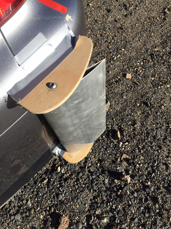
So I tried some rear Edgarwits to see if I could reduce wake size. These were additional to the front ones, and taller. GOE222 true aerofoil profile.
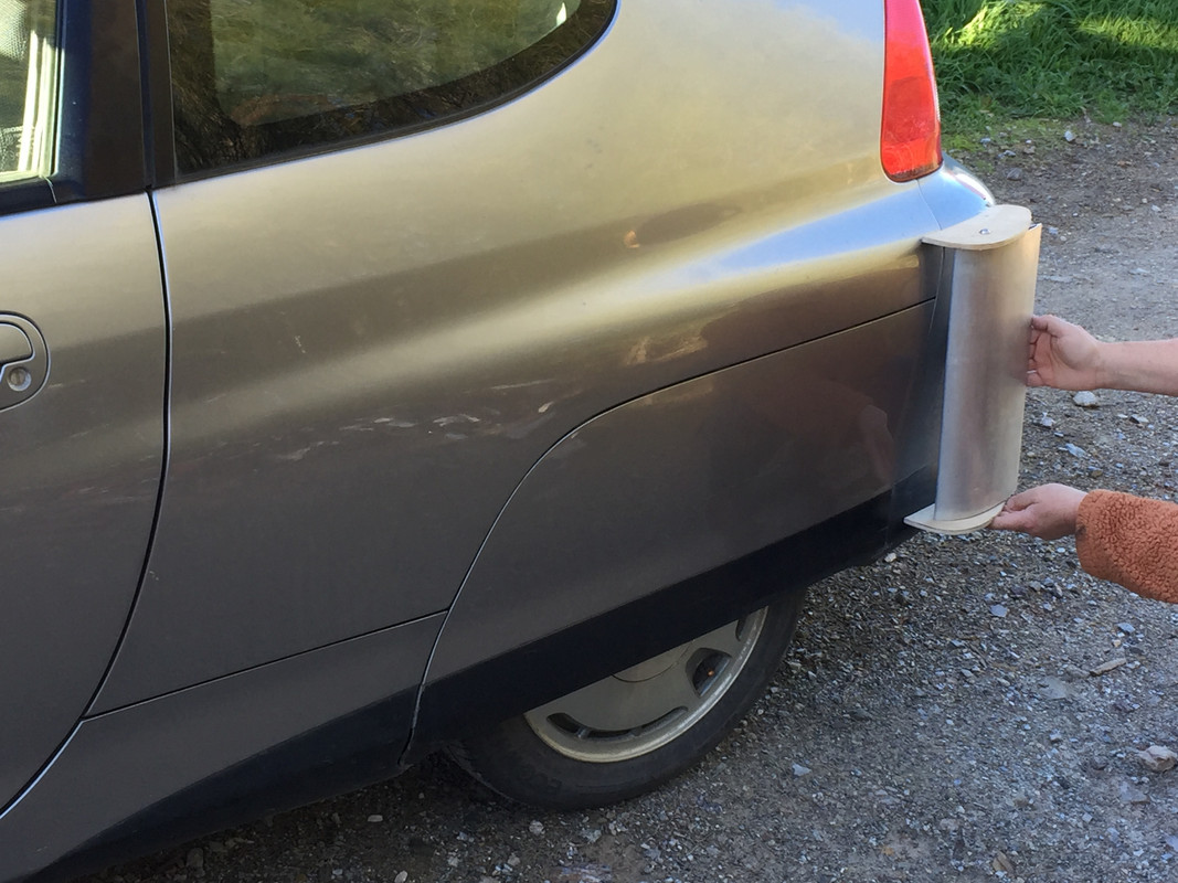
I did some throttle stop testing with the following results (km/h at 30 per cent throttle, low-moderate gusty headwind):
- No rear Edgarwits: 95
- 1 finger rear gap: 93
- 2 finger rear gap: 95
- 3 finder rear gap (ie about parallel): 96
- 4 finger rear gap (ie diverging): 96.5
That would make 4 finger vs std about 3 per cent improved in drag.
4 finger gap:
For people interested, but having other cars, don't forget Insight boat-tails a lot with its narrower rear track.
Interesting to see the better performance at the rear with the diverging duct - opposite to what occurred at the front.
I'll do some more testing on a still day, but to me this result is borderline. I'd need to see a big jump in drag reduction on a still day to go in this direction. |
Would the rear wing experiment not be just a vertical "blowen diffuser "?
What was the wind direction for the Eroding Clay test? It will help with interpretation of the results.

My interpretation based on what I see, assuming wind from the left ( American driver side)
▪ The airfoil profile has too much curve on the convex side , evidenced by severe separation less than 1/3 Cord at the bottom and 1/4 cord at the top. This would be a good application for test of VG's in a specific use case, (maintenance of attached flow in extreme angle of attack as demonstrated). I have seen a proper demonstration you're witty Edgar's work as intended to a benefit, is there room for improvement, possibly/ possible not.
¿ I'm taking it this was the downwind side?
▪ The up wind /drivers side I expect to see almost,but not quite,a poler opposite. Eg cleaned off by attached flow out side and dirty/covered by sepperated flow on the convex wing surface.
▪ the up wind turning vane / wing is acting like a blown diffuser blowing the wrong direction ,at a yaw angle between 45-180° at typical road going speeds.
E.G. By ~45° yaw (angle of attack~ 90° negative) the wing is past full stall and by ~50°ish yaw it becomes a blowen diffuser.
__________________
1st gen cummins 91.5 dodge d250 ,HX35W/12/6 QSV
ehxsost manafulld wrap, Aero Tonto
best tank: distance 649gps mi 24.04 mpg 27.011usg
Best mpg : 31.32mpg 100mi 3.193 USG 5/2/20

Former
'83 GMC S-15 Jimmy 2door 2wd O/D auto 3.73R&P
'79 Chevy K20 4X4 350ci 400hp msd custom th400 /np205. 7.5-new 14mpg modded befor modding was a thing
87' Hyundai Excel
83 ranger w/87 2.9 L FI2wd auto 18mpg on the floor
04 Mitsubishi Gallant 2.4L auto 26mpg
06 Subaru Forrester XT(WRX PACKAGE) MT AWD Turbocharged 18 plying dirty best of 26mpg@70mph
95Chevy Blazer 4x4 auto 14-18mpg
04 Chevy Blazer 4x4 auto 16-22mpg
|
|
|
|
|
05-24-2020, 05:13 PM
|
#100 (permalink)
|
|
Banned
Join Date: Nov 2017
Location: Australia
Posts: 2,060
Thanks: 107
Thanked 1,605 Times in 1,136 Posts
|
Quote:
Originally Posted by gumby79
Would the rear wing experiment not be just a vertical "blowen diffuser "?
What was the wind direction for the Eroding Clay test? It will help with interpretation of the results.
My interpretation based on what I see, assuming wind from the left ( American driver side)
▪ The airfoil profile has too much curve on the convex side , evidenced by severe separation less than 1/3 Cord at the bottom and 1/4 cord at the top. This would be a good application for test of VG's in a specific use case, (maintenance of attached flow in extreme angle of attack as demonstrated). I have seen a proper demonstration you're witty Edgar's work as intended to a benefit, is there room for improvement, possibly/ possible not.
¿ I'm taking it this was the downwind side?
▪ The up wind /drivers side I expect to see almost,but not quite,a poler opposite. Eg cleaned off by attached flow out side and dirty/covered by sepperated flow on the convex wing surface.
▪ the up wind turning vane / wing is acting like a blown diffuser blowing the wrong direction ,at a yaw angle between 45-180° at typical road going speeds.
E.G. By ~45° yaw (angle of attack~ 90° negative) the wing is past full stall and by ~50°ish yaw it becomes a blowen diffuser. |
I understand a blown diffuser to be blown only if there is external energy applied eg via a electric motor and fan.
The eroding clay was used on only one side of the car and the car was driven in lots of different directions on a day where there were gusty winds.
|
|
|
|
|
The Following User Says Thank You to JulianEdgar For This Useful Post:
|
|
|