01-18-2021, 03:08 PM
|
#51 (permalink)
|
|
Master EcoModder
Join Date: Aug 2012
Location: northwest of normal
Posts: 27,692
Thanks: 7,774
Thanked 8,584 Times in 7,068 Posts
|
Quote:
|
The depth of an unventilated box cavity for lowest drag was 0.37 * D, where D was 'effective body diameter'.
|
So that would be a planning parameter rather than a r*le of th*mb.
Quote:
|
I don't know what the above depth was, but nowhere near the 560mm I calculate from the above equation (400mm with vents).
|
Sixteen inches, more or less? Seems like a good candidate for perforating. Did you save the pieces?
Lots of experimental possibilities with slot/hole size and location.
__________________
.
.Without freedom of speech we wouldn't know who all the idiots are. -- anonymous poster
____________________
.
."We're deeply sorry." -- Pfizer
|
|
|

|
|
The Following User Says Thank You to freebeard For This Useful Post:
|
|
 Today Today
|
|
|
|
 Other popular topics in this forum...
|
|
|
|
|
01-18-2021, 03:18 PM
|
#52 (permalink)
|
|
Banned
Join Date: Nov 2017
Location: Australia
Posts: 2,060
Thanks: 107
Thanked 1,605 Times in 1,136 Posts
|
Quote:
Originally Posted by freebeard

Sixteen inches, more or less? Seems like a good candidate for perforating. Did you save the pieces?
Lots of experimental possibilities with slot/hole size and location.
|
No, I didn't keep the pieces. There is no way such an approach would be legal in this country, even if they were made of clear plastic.
You'd probably get away with it here on a box trailer or caravan though.

|
|
|
|
|
The Following User Says Thank You to JulianEdgar For This Useful Post:
|
|
|
01-18-2021, 04:31 PM
|
#53 (permalink)
|
|
Master EcoModder
Join Date: Aug 2012
Location: northwest of normal
Posts: 27,692
Thanks: 7,774
Thanked 8,584 Times in 7,068 Posts
|
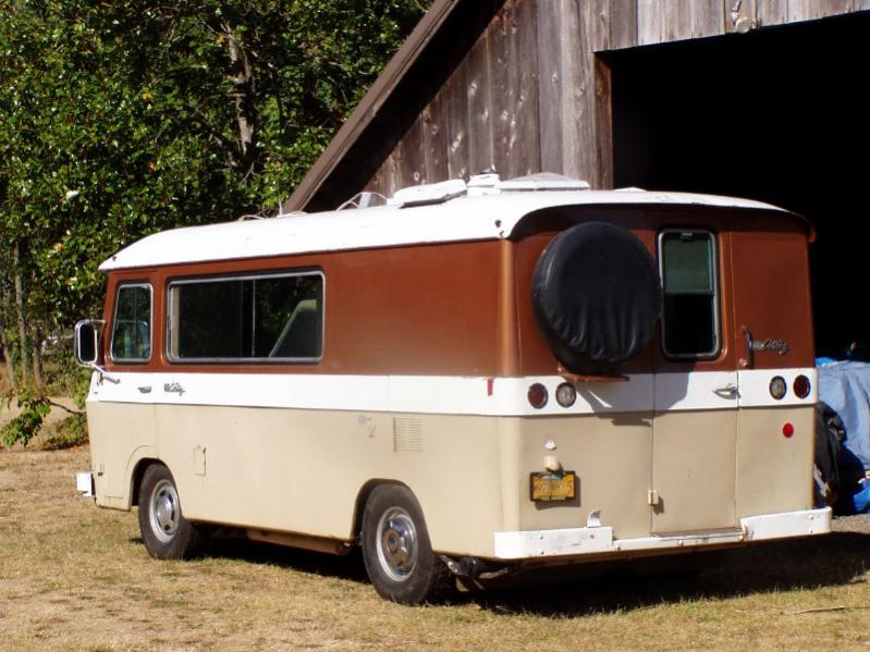
The Clark Cortez would be a good candidate, if I'd been able to hold onto it. I just found out in this interview that the Byrds had a Cortez when they came back from their England tour.
__________________
.
.Without freedom of speech we wouldn't know who all the idiots are. -- anonymous poster
____________________
.
."We're deeply sorry." -- Pfizer
|
|
|
|
|
01-18-2021, 07:08 PM
|
#54 (permalink)
|
|
Ultimate Fail
Join Date: Feb 2008
Location: Austin,Texas
Posts: 3,585
Thanks: 2,872
Thanked 1,121 Times in 679 Posts
|
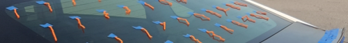
Since it seems like the NACA ducts provide a surprising amount of good velocity air, I plan to try and channel that air into the wake to reduce its' size.
Where would you all think that the ideal target area would be ?
Should I angle the airflow towards the license plate ? ( light blue lines )
Right now, they blow straight back ( yellow lines )
I also am going to go ahead and add two additional NACA ducts on each side of the box cavity now that I know their optimal placement.
And of course, I am getting a huge amount of air spillover around the lights, but I plan to have the area open for legal reasons.
I currently just have trip strips on the lights.
|
|
|
|
|
01-20-2021, 03:53 AM
|
#55 (permalink)
|
|
Ultimate Fail
Join Date: Feb 2008
Location: Austin,Texas
Posts: 3,585
Thanks: 2,872
Thanked 1,121 Times in 679 Posts
|
I was thinking that perhaps I need to have the airflow directed outwards instead of inwards.
If I have the airflow directed towards the middle of the wake, like i have in the image, this might actually just add more air to the already swirling air.
This may even make the vortexes even stronger and create more drag than if left alone.
So perhaps have the ducts angled to blow air outwards ? What do you all think ?
|
|
|
|
|
01-20-2021, 04:16 AM
|
#56 (permalink)
|
|
Master EcoModder
Join Date: Aug 2012
Location: northwest of normal
Posts: 27,692
Thanks: 7,774
Thanked 8,584 Times in 7,068 Posts
|
I think that one of the most helpful voices got themselves banned because reasons...
As to the question, it depends on what you mean by outwards. Toward the tail lights? I doubt you can do that without moving the opening. They would [migrate/morph] toward the slots that Bertone and Jaray used.
__________________
.
.Without freedom of speech we wouldn't know who all the idiots are. -- anonymous poster
____________________
.
."We're deeply sorry." -- Pfizer
|
|
|
|
|
01-20-2021, 09:13 AM
|
#57 (permalink)
|
|
Moderator
Join Date: Feb 2012
Location: Urbana, IL
Posts: 1,937
Thanks: 199
Thanked 1,802 Times in 939 Posts
|
Quote:
Originally Posted by Cd
I was thinking that perhaps I need to have the airflow directed outwards instead of inwards.
If I have the airflow directed towards the middle of the wake, like i have in the image, this might actually just add more air to the already swirling air.
This may even make the vortexes even stronger and create more drag than if left alone.
So perhaps have the ducts angled to blow air outwards ? What do you all think ?
|
Anything we can offer is purely speculative. Does throttle-stop testing work on your car? That would give an immediate indication of whether the drag force is changing and how much in each configuration. |
|
|
|
|
01-20-2021, 01:28 PM
|
#58 (permalink)
|
|
Master EcoModder
Join Date: Aug 2012
Location: northwest of normal
Posts: 27,692
Thanks: 7,774
Thanked 8,584 Times in 7,068 Posts
|
It will be interesting to see if throttle stop testing remains going forward. I'm already seeing push-back: ecomodder.com/forum/showthread.php/rule-thumb
__________________
.
.Without freedom of speech we wouldn't know who all the idiots are. -- anonymous poster
____________________
.
."We're deeply sorry." -- Pfizer
|
|
|
|
|
01-20-2021, 02:14 PM
|
#59 (permalink)
|
|
Master EcoModder
Join Date: Jan 2008
Location: Sanger,Texas,U.S.A.
Posts: 15,892
Thanks: 23,969
Thanked 7,221 Times in 4,648 Posts
|
depth
Quote:
Originally Posted by freebeard
So that would be a planning parameter rather than a r*le of th*mb.
Sixteen inches, more or less? Seems like a good candidate for perforating. Did you save the pieces?
Lots of experimental possibilities with slot/hole size and location.
|
I'm looking at Figure 8.67, on page-333, of Hucho's 2nd-edition. It's the constant-section box-cavity behind the Volkswagen Transporter.
I'm not sure if this is what's being discussed.
If so, then Hucho is using the total length ( l ) of the vehicle in relation to the depth ( x ) of the extension.
Only two data points are given.
At x / l = 0.22, the drag reduction is Cd 0.06.
Cd 0.43 - 0.06 = Cd 0.37 ( bingo! ) 
__________________
Photobucket album: http://s1271.photobucket.com/albums/jj622/aerohead2/
|
|
|
|
|