 08-17-2014, 06:42 AM
|
#911 (permalink)
|
|
Dreamer
Join Date: Nov 2013
Location: Australia
Posts: 350
Thanks: 95
Thanked 214 Times in 151 Posts
|
Quote:
Originally Posted by MPaulHolmes

What voltage is it wound for?
|
It is wound for 48 volts.
My understanding of this is very limited but i believe running a 48v motor at 96v results in twice the rpm and at 144v triple the rpm. (Overvoltaging?)
The power and torque curves obviously change between different voltages.
I can't remember all the pros and cons but when i was deciding on the voltage i exchanged quite a few emails with Custom EV Performance. I also did a lot of comparisons to the motors from HPEVS.
Too late if it is all wrong, it is in the garage waiting for the ICE engine to creep away in shame so that it can take its rightful place in the engine bay. 
|
|
|

|
|
The Following 2 Users Say Thank You to Astro For This Useful Post:
|
|
 Today Today
|
|
|
|
 Other popular topics in this forum...
|
|
|
|
|
08-17-2014, 09:28 AM
|
#912 (permalink)
|
|
PaulH
Join Date: Feb 2008
Location: Maricopa, AZ (sort of. Actually outside of town)
Posts: 3,832
Thanks: 1,368
Thanked 1,202 Times in 765 Posts
|
That was my understanding too. And at 144v, it will be far away from the 600v limit on the IGBTs, so they should last forever.
|
|
|
|
|
08-17-2014, 11:42 AM
|
#913 (permalink)
|
|
Master EcoModder
Join Date: Aug 2012
Location: northwest of normal
Posts: 27,690
Thanks: 7,774
Thanked 8,584 Times in 7,068 Posts
|
Quote:
|
100 lb for the motor, gearbox and differential is AMAZING! I may even call Toyota and ask what a replacement costs. Likely $20K but I should ask
|
This is my new favorite thing:
 http://www.fixhybrid.com/2014/04/apr...-acdc-classes/
After reading e*clipse's comment, I went down to the Toyota parts counter and asked for a part number, price and availability. Their microfische system showed a coventional FR third member in the Hybrid.  He suggested if it were available, it would run $5-8000.
My thinking runs ($8000 over base price) ==> (ignore the contoller, split 50-50 for batts and motors) ==> (split 1500-1500-1000 for the motors) ==> $1000on the assembly line ==> 5x though the parts channel; so, yeah.
It looks affordable compared to this:
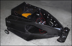
Made in Australia, it has a carbon-fiber cage in the form-factor of a Porsche 901 transaxle, a Quaife limited slip diff and heat sensors and cooling for the gearset, and about 10x the power. So I think the Highlander part should be retrofitted with a transmission cooler, for the continuous duty cycle.
Last edited by freebeard; 08-17-2014 at 11:58 AM..
|
|
|
|
|
The Following 3 Users Say Thank You to freebeard For This Useful Post:
|
|
|
08-17-2014, 12:21 PM
|
#914 (permalink)
|
|
PaulH
Join Date: Feb 2008
Location: Maricopa, AZ (sort of. Actually outside of town)
Posts: 3,832
Thanks: 1,368
Thanked 1,202 Times in 765 Posts
|
Holy cow! A regular old dual IGBT is enough for a boost converter that can do regen! I bought a 200amp 300uH inductor from Mouser a couple years ago that I could use in testing. It's not THAT heavy (it's my brother). I mean, it's ridiculously heavy, but not as just another component in a big fat car. Hmm... If you want to keep it as a separate object from the AC controller, I guess you would just need to tell the boost converter to switch to buck mode (switch connected to ground OFF, switch with the diode turned ON 100%). Then, the AC controller could command the current for regen.
I need to double-check this, but I'm pretty sure.
You don't need an input capacitor to the boost converter. Just the big fat inductor. Then, a fancy ring capacitor on the output... Maybe if the boost converter & inverter shared that cap, it would be fine. But it would need to be the same package so as to minimize stray inductance.
Last edited by MPaulHolmes; 08-17-2014 at 12:28 PM..
|
|
|
|
|
08-17-2014, 05:01 PM
|
#915 (permalink)
|
|
Permanent Apprentice
Join Date: Jul 2010
Location: norcal oosae
Posts: 523
Thanks: 351
Thanked 314 Times in 215 Posts
|
 MGR details
Awesome Pic, freebeard! 
Yup, that's what I'm using. I have several shots of a disassembled one - I have three, and took one apart so I could get some clue about it.
No, I'm not rich - I was able to source each of them from E*bay used parts places for less than $400 each. BTW, that's true with about everything - I have a Honda 1st gen Insight, and parts for it (like shocks, etc) from the dealer are silly expensive.
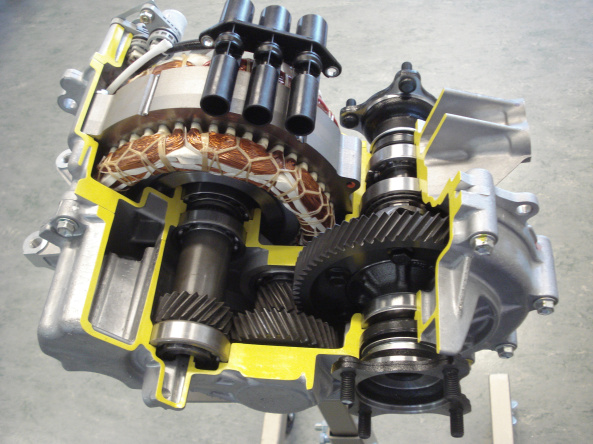
One detail that isn't apparent from the cutaway (because it's in the cutaway part) is how the oil moves in the system. It's a pretty important detail, because the motor is cooled by the gearbox oil. Basically, the oil is "pumped" by the big gear connected to the differential between the gear teeth and the gearbox case up into a small holding container. (cut away) The oil then dribbles down by gravity into other containers (cut away) that have holes to dribble oil onto the various bearings and gears. See that opening on the near side of the motor's shaft? The motor shaft is hollow, and oil is pumped (I guess) by the rotating shaft out holes in the shaft, where it sprays over the motor stator coils. That's what cools (or at least distributes the heat) from the motor.
So, if you plan to use this in a stock set-up, you ****have to***** run it with the motor forward of the differential. That's the only way the "oil pump" will work. In my Eclipse, I can do this in the front no problem, but I'm going to have to modify it with an external pump or something in the rear, because these will only fit "backwards."
My general evil plan is to integrate an oil pump and transmission cooler for the oil. As Freebeard says, this will be necessary for continuous operation. Personally, I think an agressive cooling system may allow as much as 75kW out of this.  However, I haven't found a oil pump I'm completely happy with. It must be 100% reliable, so some brushed DC motor-driven oscillating pump won't be on my car.
Another detail is control feedback. The motor uses a resolver, built into the opposite side of the motor shaft. I've messed with it a bit, getting some beautiful sin waves of the motor's position. There's also temperature feedback in another connector.
- E*clipse
Quote:
Originally Posted by freebeard
This is my new favorite thing:
April 2014
One more HEV for ACDC Classes | Auto Career Development Center
After reading e*clipse's comment, I went down to the Toyota parts counter and asked for a part number, price and availability. Their microfische system showed a coventional FR third member in the Hybrid. He suggested if it were available, it would run $5-8000.
My thinking runs ($8000 over base price) ==> (ignore the contoller, split 50-50 for batts and motors) ==> (split 1500-1500-1000 for the motors) ==> $1000on the assembly line ==> 5x though the parts channel; so, yeah.
It looks affordable compared to this:
Made in Australia, it has a carbon-fiber cage in the form-factor of a Porsche 901 transaxle, a Quaife limited slip diff and heat sensors and cooling for the gearset, and about 10x the power. So I think the Highlander part should be retrofitted with a transmission cooler, for the continuous duty cycle. |
|
|
|
|
|
08-17-2014, 05:24 PM
|
#916 (permalink)
|
|
Master EcoModder
Join Date: Aug 2012
Location: northwest of normal
Posts: 27,690
Thanks: 7,774
Thanked 8,584 Times in 7,068 Posts
|
I hope it doesn'r sound like I know what I'm talking about. MPaulHolmes last post, for instance, went right over my head.
It's awesome that you have some in hand. What are the dimensions? I'd like to site one to replace a VW transaxle.
Have you sorted out the U-joints and half-shafts?
|
|
|
|
|
08-17-2014, 05:45 PM
|
#917 (permalink)
|
|
Permanent Apprentice
Join Date: Jul 2010
Location: norcal oosae
Posts: 523
Thanks: 351
Thanked 314 Times in 215 Posts
|

Perhaps I'm confused?
It kind of looks like the drivers are (electrically) connected to the control by components. Are there any other connections that aren't obvious (perhaps in the other 2 hidden layers?)
If not, perhaps those drivers could be cut out and some clever plug connect them to the driver board? Or maybe that's a silly idea for some other reason?
- E*clipse
Quote:
Originally Posted by MPaulHolmes
The 6 drivers are on the same board, but have built in very high isolation and common mode noise immunity. It's the FOD8316. FOD8316 Fairchild Semiconductor | Mouser
it also has a desaturation isolated fault signal that goes right to the micro and a hardware fault circuit. Being a 4 layer board with no traces on the internal +5v and ground planes, all signal paths have a very small loop area. Also all signals are separated sufficiently so as not to cause cross talk. There are no cables that could pick up noise. Also, all signals that are square waves don't change sides of the board since they radiate at sharp points. I'll post the hole coordinates tomorrow. Typing on phone. Hate tiny buttons!!! Haha |
|
|
|
|
|
08-17-2014, 06:03 PM
|
#918 (permalink)
|
|
Permanent Apprentice
Join Date: Jul 2010
Location: norcal oosae
Posts: 523
Thanks: 351
Thanked 314 Times in 215 Posts
|
Ummm, regarding dimensions, as you can see from the pic, they're pretty oddly shaped. What dimensions would you like?
Regarding U-joints and half-shafts: There is a local guy who makes custom driveshafts for people's rock crawler rigs locally. My last project required a front driveshaft (for a VW TDI diesel Toyota pickup) and I was really happy with his work.
I have the halfshafts and CVT's from my Eclipse, I just need the replacement CVT's from the Highlander. Basically, I'll bring the shafts with the CVT's and a length and this guy ( High Angle Driveline ) will turn out a perfect, balanced, driveshaft.
-E*clipse
Quote:
Originally Posted by freebeard
I hope it doesn'r sound like I know what I'm talking about. MPaulHolmes last post, for instance, went right over my head.
It's awesome that you have some in hand. What are the dimensions? I'd like to site one to replace a VW transaxle.
Have you sorted out the U-joints and half-shafts?
|
|
|
|
|
|
08-17-2014, 08:06 PM
|
#919 (permalink)
|
|
Master EcoModder
Join Date: Sep 2010
Location: Saskatoon, canada
Posts: 1,488
Thanks: 749
Thanked 565 Times in 447 Posts
|
Quote:
Originally Posted by MPaulHolmes
Holy cow! A regular old dual IGBT is enough for a boost converter that can do regen!
|
Trying to follow along ...
A dual IGBT can run a boost circuit - yup - I got that part. Now for the part I missed .. 'that can do regen' I guess I missed that part.
Quote:
Originally Posted by MPaulHolmes
Hmm... If you want to keep it as a separate object from the AC controller, I guess you would just need to tell the boost converter to switch to buck mode (switch connected to ground OFF, switch with the diode turned ON 100%). Then, the AC controller could command the current for regen.
|
If you are boosting a battery pack, the input, and the output is a higher voltage, the circuit can cut back on the boost when the regen is raising the voltage ... but how can the current flow back into the pack when that battery pack is on the input terminal?
Quote:
Originally Posted by MPaulHolmes
You don't need an input capacitor to the boost converter. Just the big fat inductor. Then, a fancy ring capacitor on the output... Maybe if the boost converter & inverter shared that cap, it would be fine. But it would need to be the same package so as to minimize stray inductance.
|
I would be OK with a boost converter built into the input of the AC controller ... still having trouble with the regen part though. |
|
|
|
|
08-17-2014, 08:38 PM
|
#920 (permalink)
|
|
PaulH
Join Date: Feb 2008
Location: Maricopa, AZ (sort of. Actually outside of town)
Posts: 3,832
Thanks: 1,368
Thanked 1,202 Times in 765 Posts
|
Have the low side be the low side switch in the boost converter. The inductor connects to the collector of the low side switch. Now, the high side IGBT has the diode built in from high side emitter to high side collector. That's the regular diode in the boost converter. The high side switch is what allows the regen to go to the batteries. During regen, low side IGBT off, and high side IGBT on with 100% duty.
|
|
|
|
|
The Following User Says Thank You to MPaulHolmes For This Useful Post:
|
|
|


