07-19-2009, 11:32 PM
|
#2041 (permalink)
|
|
EvEagle
Join Date: Apr 2009
Location: Lansing, MI
Posts: 40
Thanks: 0
Thanked 7 Times in 4 Posts
|
Hey, Paul.. checking out your BOM parts list; I wonder if there's a mistake in the power mosfet listed on the Power section. It lists a IRFP4468PBF, which is listed on data sheets as 100 volts; but I believe it should be the IRFP4668PBF, the 200 volt one.
Evan
|
|
|

|
 Today Today
|
|
|
|
 Other popular topics in this forum...
|
|
|
|
|
07-19-2009, 11:38 PM
|
#2042 (permalink)
|
|
EcoModding Lurker
Join Date: Mar 2009
Location: Victoria Australia
Posts: 30
Thanks: 0
Thanked 4 Times in 2 Posts
|
Clutchless
jmcginley
My 1985 Camira is clutchless, I can change from third to fourth or fourth to third by just lifting off the throttle, I only need second gear on a steep hill following a tight bend for this I try to anticipate and select second while stopped, adjusting revs is difficult. I have been using a Curtis 1231c and after that blew up a Logisystems 144V controller, with these I need the lower gear for low speed on a steep rise, I am hoping that Paul's controller will be better.
John
|
|
|
|
|
07-20-2009, 12:05 AM
|
#2043 (permalink)
|
|
PaulH
Join Date: Feb 2008
Location: Maricopa, AZ (sort of. Actually outside of town)
Posts: 3,832
Thanks: 1,368
Thanked 1,202 Times in 765 Posts
|
Thanks, edown! BOM fixed!
I mean it would be better to change the 5 hole bus bars to 4, but not necessary. It wouldn't be "better", it would just be less drilling of heat spreader, but maybe just leave it! hehe. It doesn't matter.
Holy cow! I just noticed something! On the back side, the 4 U shaped etches that separate the capacitors should extend down to contain the holes for B+. Then, there doesn't need to be any isolation for B+. The plated vias would be very helpful then (since B+ is right above that). Then I also use brass bolts to further help conducting from bottom to top for B+. At least, this is how I did it with the 3 prototypes, and Ben's is working really well in my car right now.
There would still need to be the isolation etches around the M- holes. Good thinking! They are going to put in plated vias!? That would take off like 1 or 1.5 hours of work soldering! Also, if 4 ounce copper is used, then the bottom side of this design will basically behave like 8 ounce copper during much of the trip from B+ to B- (it's sort of a long story why, must do grading for school tomorrow! aaaahhh!)
MCUDOGS! YOU ARE THE MAN!
Last edited by MPaulHolmes; 07-20-2009 at 12:26 AM..
|
|
|
|
|
07-20-2009, 07:26 AM
|
#2044 (permalink)
|
|
EcoModding Lurker
Join Date: Jun 2009
Location: Australia
Posts: 35
Thanks: 0
Thanked 3 Times in 3 Posts
|
Paul, You're not just a pretty face! That's a good idea about extending the B+ down to the mounting holes and also reducing the drilling of the bus bars, both included on next version, see attached.
I've calculated the maximum current for the layout using 4 oz cu and it should be 1200A (120A / FET) with a maximum temp rise of 20 deg C.
Can you tell me the dimensions of the bus bars? I want to check clearances for the components.
I got a quote for 50 off of the power boards and it worked out at about $12 each. I don't really want to do a prototype of the board as it will cost about $160 in one off quantities. I will just have to double check everything before ordering them.
Last edited by mcudogs; 07-20-2009 at 08:03 AM..
|
|
|
|
|
07-20-2009, 11:06 AM
|
#2045 (permalink)
|
|
EcoModding Lurker
Join Date: Aug 2008
Location: Calgary, AB
Posts: 21
Thanks: 1
Thanked 1 Time in 1 Post
|
dcb,
The motor voltage or Back EMF does relate to the rpm.
Here are some good links.
Back-EMF Motion Feedback
http://www.st.com/stonline/products/...e/an/10775.pdf
The pdf is for 3 phase brushless DC, but has much more detail.
To detect the back emf, we have to wait for the current to drop to zero, otherwise the flyback diode holds the voltage down to Vd. (Figure 5 in 10775.pdf).
But if we space out the voltage reads enough, this is totally viable. |
|
|
|
|
The Following User Says Thank You to dlaing For This Useful Post:
|
|
|
07-20-2009, 11:49 AM
|
#2046 (permalink)
|
|
PaulH
Join Date: Feb 2008
Location: Maricopa, AZ (sort of. Actually outside of town)
Posts: 3,832
Thanks: 1,368
Thanked 1,202 Times in 765 Posts
|
mcudogs, I just can't think if any more criticisms! It looks good to me! So, this is what people do, hanging out at home with their $10,000 software? hehe.
Oh man, one more thing that isn't required, as I didn't do it on the 3 prototypes. It might make the assembly easier, however. 2 vias near B- for the 2 ground wires that connect to the power ground of the control board. The placement of the holes should be so as to make them as close to the holes in the control board. I have to leave for school, but maybe on the wiki you can see where the 2 holes are on the control board, and figure out where they should be on the power section. I just surface mounted the 16 gauge wire (or whatever it was), which was a bit of a pain.
|
|
|
|
|
07-20-2009, 09:00 PM
|
#2047 (permalink)
|
|
PaulH
Join Date: Feb 2008
Location: Maricopa, AZ (sort of. Actually outside of town)
Posts: 3,832
Thanks: 1,368
Thanked 1,202 Times in 765 Posts
|
MCUDogs! One more thing! This is more serious. Notice that on the top, the gate pads start on the left next to the edge. That is correct. But notice on the bottom. That same gate pad should be really close to the RIGHT side, but there is no gate pad near the right edge. I made that same mistake before. So, the tops and bottoms of each of the gate pads should coincide.
OK, now let's consider the bottom of the power section:
The 2 holes for the ground wires (which I have never had before, but would simplify the assembly process) should go just to the left of the 2nd gate pad (starting from the right side) and to the left of the 7th gate pad (starting from the right side). If you decide to do the holes, they should be big enough for maybe 16 gauge wire I think. I don't know the exact size. Can you find the hole sizes from the control board fab files? I don't have a way to read them.
Last edited by MPaulHolmes; 07-20-2009 at 09:05 PM..
|
|
|
|
|
07-21-2009, 12:15 AM
|
#2048 (permalink)
|
|
PaulH
Join Date: Feb 2008
Location: Maricopa, AZ (sort of. Actually outside of town)
Posts: 3,832
Thanks: 1,368
Thanked 1,202 Times in 765 Posts
|
I have basically confirmed today that the rubber spider in my coupler is sort of messed up now. All that 0 HP to 45HP to 0 HP driving to try to get the overcurrent to come on. Also, from having the e-brake on and pulsing the motor (bucking bronco) to get the PI loop tuned sort of caused problems too hehe. It was fun though. I think I'm going to order a new spider insert on the 25th. This time it will be bronze! Very much not as squishable as rubber. Maybe that's a bad idea. Maybe I should get that inbetween one, harder than the black rubber, but wimpier than the bronze.
http://cgi.ebay.com/ws/eBayISAPI.dll...tab%3DWatching |
|
|
|
|
07-21-2009, 02:02 AM
|
#2049 (permalink)
|
|
Joe
Join Date: Feb 2009
Location: phx
Posts: 260
Thanks: 0
Thanked 48 Times in 38 Posts
|
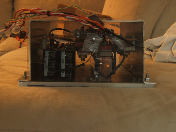
it works! It took a while to install, but I accomplished a bunch of stuff. I had to move the heatsink out aways to make room for the mounting flanges and while I had everything apart, I tinned the bus bars. I also put together a simple 4 probe temperature gauge. it uses an atmega16 that i had laying around and 4 thermistors and just scrolls through the temperature readings on an LED display.
This shows the rear of the controller with 3 of the 4 probes in the controller. I had one taped to a capacitor, another wedged in between the space above a mosfet, and another wedged in between the space above a diode. I used folded up paper to wedge it in there so that the thermistor was pressed against the top of the mosfet/diode case.
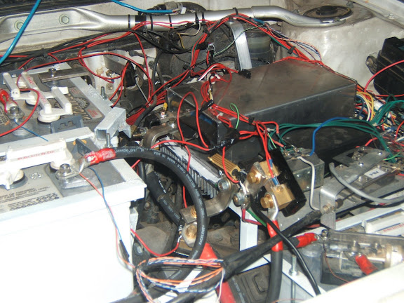
Installed in the car amongst the web of wires...
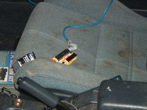
The temp probe circuit and display just sits in the front seat for now...
The coolest thing for me has to be the silence when moving slow... I'm too used to the curtis and its squeal!
Paul, I noticed the 'bucking bronco' phenomenon that I think you mentioned before. I'd guess that the control loop is acting too fast and gets into an oscillation - it sounds like you have it worked out, so i'm anxious to try out the new loops.
The accelerator position = torque thing is quite different. I'm used to having to press the pedal ever so slightly and then press further and further to go faster and faster. Now, it's almost the opposite! I have to press the pedal deeply and then release it as the car accelerates.
I only took a few trips around the neighborhood (got a little late), but i did get a little bit of temperature data. Ambient temp = 34C. I did 8-10 accelerations to 25 mph pulling 200-400 amps each and I noticed the mosfet and diode temp get up to about 60C while the cap temp seemed to stay lower in the low 40's (don't remember). I want to double check the accuracy of my probes, but I think they're pretty good.
More testing to come! |
|
|
|
|
The Following User Says Thank You to jyanof For This Useful Post:
|
|
|
07-21-2009, 02:34 AM
|
#2050 (permalink)
|
|
EcoModder Student
Join Date: Nov 2008
Location: Youngsville, NC
Posts: 117
Thanks: 11
Thanked 14 Times in 13 Posts
|
Congratulations jyanof, so far that is good news!
I think we all know that Paul has a VW with 72 volt system. For my feeble self, I can't remember if you spelled out your specs. What are the basics of your EV? Model, drive train, weight? That will help in the comparisons.
Thanks,
Eric
__________________
1995 BMW 318i EV in the making
|
|
|
|
|