Quote:
Originally Posted by freebeard

That's what I'm saying is odd. I'd expect a web page to vary but not a PDF. I ganked this from the file for purposes of discussion.
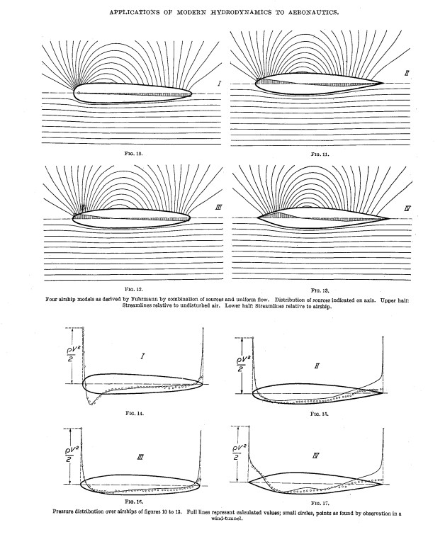 Distribution of forces indicated on axis
Does this mean the center of rotation is at midchord for figs. 11-13, and center of rotation in fig. 10 the nose tip?
Streamlines relative to undisturbed air
Are these not isobar lines? |
All four are streamline bodies of revolution.
All four contours are revolving around their central axis.
------------------------------------------------------------------------------------
This research appears in at least two other publications.
My original 'look' came in Dr. Hermann Schlicting's book, Boundary-Layer Theory. Dr. Wolf Heinrich Hucho was assistant to Dr. Schlicting for eight years, at the Technical University, Braunschweig, where Hucho studied mechanical engineering.
It's also in, ELEMENTARY MECHANICS OF FLUIDS, by Ph.D. Hunter Rouse.
They all depict 'pressure distribution' both numerically derived from inviscid flow models and then actual wind tunnel measurements, which address the D'Alembert paradox. The first of it's kind!
In the NACA images, the vertical values within the 'arrows' are from zero-to-unity.
The zero value occurs at the axis of each shape. It's completely arbitrary.
Schlichting 'raised' the airship's axis up to the 80% line, to unclutter the image a bit.
All the 'small circles' coincide with their representative piezometer orifice static pressure port on the wind tunnel model, or numerical model.
'Circles' below the zero line are negative pressures as compared to the chosen reference pressure datum.
Everything is drawn to scale, and one can draw in a high resolution cartesian grid to ease quantifying each individual measurement. ( that's what I do ).
--------------------------------------------------------------------------------------
The 'center' of each circle defines the demarcation of a specific local incremental/ perturbation-induced pressure, caused by the presence of the body in the free stream, from which a 'candy-stripe' iosobaric 'contour' map can be constructed.
------------------------------------------------------------------------------------
I'm slowly going through an inter-comparison of the math of all three presentations. All three use different 'metrics.' There are symbols used which I've never seen before. They're not Greek, or in the normal alphabet.
Plus, there's terminology I've never experienced.
There's even a 'spread' on the reported Reynolds number.
Typically, 'unity' is reserved for 'Total pressure' ( point of stagnation ), including local station pressure @ infinity, along with any dynamic -pressure ( ram-air ) component.
-------------------------------------------------------------------------------------
If one examines the Cp profile of the Tesla Model 3 that we have access to, compared to that of the 1978 D-B, M-B, C- 111 III long-tail, you see that the Mercedes is generating rear pressures of the Tesla, without any rear spoiler, and the pressure map of the streamline bodies indicate for positive pressures over their rears, compared to 'neutral' for the Mercedes, and 'negative' for the Tesla, which is perfectly logical, in the context of a streamline body's pressure recovery.


 Today
Today