Quote:
Originally Posted by Vman455

*sigh*
Okay. What aerohead is arguing is that if we have a curve, a surface that is not the same shape as the curve but intersects it at 2 points will have similar or the same flow over it (hence the list of cars that supposedly intersect his template in profile view). Graphically:

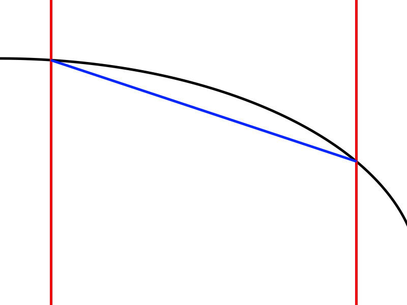
Let's assume this curve has attached flow over it, and bisect it at two arbitrary points upstream and downstream of its average inclination and assume the car body ends at the line to the right:

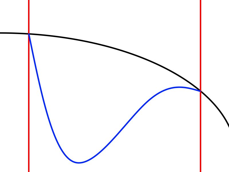
Replace this curve with a flat surface intersecting it at the two red lines:
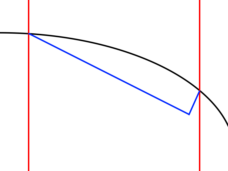
Or replace it with a flat surface that has a steeper angle of inclination and a spoiler, extending or standing up so that it still intersects the curve:


The argument is that the "outer" airflow will still follow the shape of the curve, not the real surface, that flow will recirculate on the real surface, and that the pressure on the real surface will be lower in front of the spoiler, higher in the "outer flow," and higher behind the spoiler, on the base.
First problem: this isn't how spoilers work. You can see this on your own car if you tape spoilers of various heights and shapes to it along with tufts on the rear window, and measure pressures on the window and base:

Here, a spoiler does not cause the flow to recirculate on the window (or even just ahead of the spoiler) and outer flow to "skip" over the surface in a more-perfect "template" shape. The car has attached flow over the window with or without this spoiler, despite its having a faster curve than the "template" (which tells us something about the "template's" ability to predict attached and separated flows, another of its claimed uses on this site...). With the spoiler in place, pressure increases on the window (and roof) ahead of it.
Further, take this argument to its logical conclusion: if the airflow will follow a "perfect" shape regardless of the actual body shape between these two points, then these:


...would be aerodynamically identical to the actual curve. This is simply not true. Aerodynamic parameters such as pressure and velocity are path-dependent. In other words, it matters what happens between two points, not just at the points. |
Thanks for showing up, we've got a lot to talk about.
And thanks for the graphics, that's good work, and it pleasing that you're 'drawing.'
-------------------------------------------------------------------------------------
I can work with your images. They're an okay start, however being 'disembodied' from the rest of the car and ground plane may confuse some, and we can only talk qualitatively, there's no facility to quantify anything, so at some point we need to get 'real.'
--------------------------------------------------------------------------------------
Compared to any of the three 'templates' your 'curve', and the hypothetical cars you've depicted are so radical that I don't really know what to say with respect to what you're saying that I'm saying. But I'll keep going and see if I can navigate your images.
--------------------------------------------------------------------------------------
And since the ASTs are primarily for 'modifying' existing mass produced vehicles, which happen to share an embryonic roofline contour with at least one of the three templates, it would be less confusing to members and guests if you could include maybe a dashed line to each 'blue' contour, which signifies some original OEM contour which we'd be attempting to improve upon. (Some context in keeping with the premise of the 'templates' ).
--------------------------------------------------------------------------------------
1) For all the 'cars' shown, by reaching up, with a spoiler, through the separated flow, to the 'reversal point' at the AST, the flow would reattach at the tearing edge of the spoiler.
-------------------------------------------------------------------------------------
2) According to Professor Hoerner, between the original separation line and the newly created tearing edge, a containment would be created for a new stationary vortice to be captured, over which the inviscid flow would proceed rearwards, decelerating over the vortice, which itself would consume but little momentum from the over-arcing flow.
-------------------------------------------------------------------------------------
3) The decelerated flow acting against the spoiler would communicate the higher static pressure of the 'wider-spaced', slower-moving, higher static pressure ( Bernoulli Theorem ) local streamline, to the vehicle's body, leaving a wake of higher base pressure, lower pressure drag, and lower total drag.( it's a fact for the ASTs, I can't vouch for the contour shown )
--------------------------------------------------------------------------------------
4) 'when the ( rear spoiler) height is too low the (separated) flow does not reattach on the ( trunk/boot ) lid.' Max Schenkel, aerodynamicist, General Motors Corp..
--------------------------------------------------------------------------------------
5) Beyond the tearing edge of the spoiler, the attached flow continues along the streamline pathway, to its conclusion.
--------------------------------------------------------------------------------------
6) In the 3rd image from the top, the angled, straight red line spanning the 'goal posts' returns the lowest drag for the 1975 VW Golf/Rabbit when Hucho et al. matched this angle to the AST, yielding a drag, 28.5 % lower than what Giorgetto Giugiaro ultimately chose for production. Cd 0.43 vs Cd 0.34.
-------------------------------------------------------------------------------------
7) The 4th image from the top would be an analogue for what was done to correct the lift and drag of the 2011, Audi A7.
Again, the AST was chosen ( unknowingly ) for the pop-up rear spoiler, as with the 1972 Porsche 911 Carrera RS 2.7 'Ducktail' .
------------------------------------------------------------------------------------
8) The 5th image down could represent the 1972 Carrera.
--------------------------------------------------------------------------------------
9) Image 6, from the top, would be a perfect analogue for SAE International's
' Effective Back-Light Angle ( EBLA ) mentioned in Julian Edgar's 'Modifying... book, from Adrian Gaylard, Jaguar Land Rover, in which Gaylard suggested an optimum 12-degree slope angle for lowest drag, likely borrowed from FIAT's 1986 SAE 860212, in which his 'optimum' 12-degree EBLA also happen to fall exactly on an AST contour.
--------------------------------------------------------------------------------------
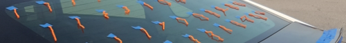
10) The Prius-III tuft study may be problematic within the context in which what is shown may be downwash flow rather than actual 'attached' flow.
For the 1972 Porsche 911 it was pretty obvious, with the 2011 Audi A7, not so much.
Vman455's comment about the auxiliary spoiler increasing the pressure over the Toyota's rear in indicative of a downwash situation( if the original flow were attached, this area would already be at a static pressure maximum, on account of the Bernoulli Theorem, and widest-spaced streamlines ).
Adding a spoiler, and 'pinching' the streamlines back closer together and then experiencing a pressure increase from a faster-moving flow would be impossible if fully-attached flow had been present in the first place ( one cannot decelerate a fully decelerated flow ).
Logic suggests that the added spoiler served to 'create a stronger negative pressure gradient', as with the Porsche 911 and Audi A7 (Dr.-Ing. Wolf-Heinrich Hucho & Dr.-Ing. Thomas Wolf ).
--------------------------------------------------------------------------------------
11) Something else, germane to the Prius-III, is that this exact car was tested consecutively with Spirit of EcoModder at the wind tunnel, in 2014, as a full-scale wind tunnel blockage-ratio calibration model; for comparison to A2 Wind Tunnel data, and Toyota's full-scale wind tunnel data.
Spirit had about 6% lower drag than the Prius, but more interesting, it had 62% lower rear lift than the Prius, and that's without any kind of rear spoiler, which demonstrates the pressure recovery capability of the AST's contour.
At 130-mph, Spirit also had half the rear lift of what the 'notchback' Mercedes-Benz CLA250 generated at 70-mph, which calls into question, the concept of 'wrapped flow' as associated with fastback lift.
--------------------------------------------------------------------------------------
12) With respect to the last three contours and the air following 'as along the perfect shape' and being as good, with respect to lift and drag, as the streamline contour:
They'll likely do as Professor Hoerner suggests.
I don't recall ever saying, or implying that a spoiler mod could match that of a streamline contour, only that, ' The attached spoiler would provide nearly the same drag and lift coefficients as raising the ( body's ) upper rear edge', and in the context of the geometries what Hucho reported for the GEN-1 VW Scirocco, on page-175, 2nd-Edition, Aero. of Road Vehicles.
------------------------------------------------------------------------------------
13) With respect to the last image at the bottom of Vman455's graphic, this severely mutilated aft-body would have special significance to mutilated streamlined bodies.
Abbott & Von Doenhoff provide an interesting glimpse into mutilation vs delta-Cd phenomena, in Figure 134, on page-228 of their 'THEORY OF WING SECTIONS.
A Clark Y airfoil of Cdmin 0.0152 is depicted at the top of this graphic, followed by this same wing section mutilated with varying numbers and locations of slats, slots, flaps, and trim-tabs.
These horizontal 'openings' in the wing constitute 30% of the wing's thickness each.
* a single 'hole', at 1/3rd chord increases drag from Cd 0.0152, to Cd 0.0199, a 31% drag penalty.
* Moved to mid-chord, the 'hole' causes a reduced penalty, @ Cd 0.0188, a 23.6% penalty.
* Moved to 2/3rds chord, the least 'damage' is done, with the mutilation registering Cd 0.0164, a 7.9% penalty.
The aircraft remains in flight, albeit with a higher power requirement, as a tradeoff for tremendous lift coefficients ( induced drag ).
Flow separates at each 'hole', then reattaches for the remainder of the wing. The pocket of 'dead air' just trains along within the wing, as rail cars do within a railroad train, or double, or triple trailers behind an 18-wheeler.
--------------------------------------------------------------------------------------
14) My almost last remark returns to the issue of lift, as related to streamlined bodies.
In a comment like ' ... as we know, faster-travelling air generates lower pressures- and so, in this case, lift.' we need to be very careful to provide the context / conditions to the reader.
In ' THEORY OF WING SECTIONS' we're introduced to 118-families of airfoils, and for all cases, each family possesses a condition for zero-lift.
Even with the cambered shape, and accelerated flow over the top of the wing, any lift due the suction peak, is cancelled by the leading and trailing edges of the airfoil.
With the example of one thickness of the Clark Y airfoil, the coefficient of lift is zero for an angle of attack ( AOA ) of negative 5.6-degrees, and it achieves its minimum Cd 0.0128 as well.
At AOA = positive 15.6-degrees, it reaches its maximum lift coefficient of Cl 1.425, at Cd 0.1500, a drag increase of over eleven-hundred percent.
-------------------------------------------------------------------------------------
15) As to 'lift' of the 'templates,' if you divide the distance around the bodies into 53- pressure tap locations, for the longtail templates you'll basically see:
* From the forward stagnation point, to between taps # 6 and 7, the pressure is positive.
* From '6.5' rearwards, pressure falls below zero.
* The suction peak occurs @ tap# 18.
* Beyond #18, the pressure rises again, passing zero between tap # 40 and 41.
* From there, it's back in positive pressure territory for the last 22.6% of the body. And since, on a vehicle, this puts it in 'overhang' beyond the rear axle, it's producing a torque ( 'moment' is used in engineering ), amplifying its effect.
Jeff Howell et al., at Loughborough University are presently testing primitive versions of streamlined tails on a Windsor body. There's an initial low pressure due to a lack of transition to the tail, then from there rearwards, pressure increases as the flow decelerates and gains pressure. We'll see this on Cybertruck when it's released for 3rd-party testing.


 Today
Today