09-03-2012, 11:37 PM
|
#1 (permalink)
|
|
EcoModding Lurker
Join Date: Sep 2012
Location: United States
Posts: 9
Thanks: 0
Thanked 0 Times in 0 Posts
|
Aerodynamic Bed Cap Add On-- UPDATE w/pics!
Please bare with the lengthy post. Thanks 
Hello, Im new here but love the site already. I'm 22 and own my own auto repair shop which I have to temporarily close the doors on for various reasons. Among this time off I have decided to do something I have always wanted; travel the U.S. ending up in California and bumming on the beach for a while. I will be taking a 1997 for ranger 4cyl 5spd. I will also be living out of the bed. Fuel mileage is of concern with as many miles being driven I see an opportunity for huge savings.
Please I need some advise so I can get started on building as I leave oct 1st. I am doing some of the regular stuff like covering the wheel wells, adding full moon hub caps, molding a semi-sphere onto the front of my mirrors, blocking off the grill, tire pressure, ect.... ect.... ect.... my biggest challenge is making a boat tail. I will be making a carrier basket for the rear that will be a big aluminum box like a tool box to store some stuff in and see how i can use this as shape to extend the boat tail further past just the rear bumper. problem is the truck has a cap that will stay in place as i will be sleeping there. My idea is to add an air foil to the top of the cap playing off the natural curve of the windshield and sloping down to the carrier(which will also be sloped in design and align with cap foil).
FINAL QUESTION!; is this being counter productive as i am adding more frontal area? or.. will the effect of the boat tail outweigh the extra frontal area? Attached is a pic of my truck with pvc laying on top that would be the structure & shape for the foil. The other pic is the exact outline of the truck shape with the cap, air foil leading into the carrier. to me it looks very good but I am still young and dumb and looking for some advice from some pro aero-guru's.
Thanks guys for any help. I will be updating with many pics throughout the build. Like I said I own a shop and am kind of picky about the things I build looking as nice as they function. Having all necessary machining equipment I plan on it looking very clean and refined. oh, my website is joshsautorepair.webs.com Thanks again!
Last edited by caliboundranger; 09-09-2012 at 10:48 PM..
|
|
|

|
 Today Today
|
|
|
|
 Other popular topics in this forum...
|
|
|
|
|
09-03-2012, 11:44 PM
|
#2 (permalink)
|
|
EcoModding Lurker
Join Date: Sep 2012
Location: United States
Posts: 9
Thanks: 0
Thanked 0 Times in 0 Posts
|
clarification
To clarify, the full boat tail will go about 6" past the end of the pvc pipe, this area between the end of the bed and the end of that pipe are occupied by the homemade hitch carrier. Essentially one unit when done contouring into one another to complete the boat tail. Also wondering if the sides(driver and passenger as looking at it from back) should slope in(toward the center) as well. Looking for any and all feedback, questions, or concerns. Thanks again.
|
|
|
|
|
09-04-2012, 01:26 AM
|
#3 (permalink)
|
|
Aero Deshi
Join Date: Jan 2010
Location: Vero Beach, FL
Posts: 1,065
Thanks: 430
Thanked 668 Times in 357 Posts
|
Welcome Josh,
You have a good idea, and your instincts aren't too far off. I think you may actually benefit from adding frontal area. Here's why, the "break over" angle at the top of your front glass is awful. (Red Line Bottom Pic) If you notice, I don't think any modern vehicle does this anymore. So if you built up, it will give you a chance to soften this and make it great. This will also allow you to follow the template, (Blue Line) which affords the optimum aero drag reduction, to the back edge of your cap. If you build the extension onto that following the curve, you'll really have something that works.
You could leave the "Top Foil" (Green Thing on Top) out and minimize the frontal area by just building the extension (Green Thing on Back) carefully. (Bottom Pic) Notice it is difficult to know where to place the template, I put it where it felt about right to me. But I purposely curved the extension a little below it, but not much, I have seen this done on some modern vehicles and can't help but think going sub-template on a longer overall shaped vehicle tends to help minimize the wake area without creating too dramatic a breakover.
Your shape in the picture you provided as a "How's This" is far too sudden of a break at the peak, this I feel would not work too well, if at all.
Also take note of the up slope on the bottom of the extension, this was not an accident, you want to taper up in this "Rear Diffuser" area at about 10°. This will help a lot. Speaking of this, you may want to consider figuring out a way to attach a large rear extension by something other than just the hitch receiver, I think you'd be putting too much stress on the receiver and box. You may want to consider something which goes into the rear stake holes on your truck bed and goes back to help stabilize that load.
And Yes, you do want to taper in the sides of any rear extension, you dont have to be very dramatic in how much it tapers in, about 8°-10°, but you for sure want something.
Anyway, here's my 2¢ in a picture to start the ball rolling. I bet a donut a bunch of folks don't like the idea of adding any height at all no matter the logic. Top Pic

The Ecomodder forum has funny limits on how big an image can be to save space I presume, anyway, here is a link to a bit bigger version of this same drawing.
Bigger Pic to Study |
|
|
|
|
09-04-2012, 06:47 AM
|
#4 (permalink)
|
|
Master EcoModder
Join Date: May 2008
Location: Maynard, MA Eaarth
Posts: 7,907
Thanks: 3,475
Thanked 2,950 Times in 1,844 Posts
|
This is always a choice between practicality and drag -- if you cannot do without all the space in your existing cap, then adding an arched top will probably help the overall drag, even if it adds frontal area (as Chaz says). But, if you can live with a smaller volume under the cap, then truncating the existing cap will definitely be better.
|
|
|
|
|
09-04-2012, 12:15 PM
|
#5 (permalink)
|
|
EcoModding Lurker
Join Date: Sep 2012
Location: United States
Posts: 9
Thanks: 0
Thanked 0 Times in 0 Posts
|
I definitely need all the space under the cap as I will be basically living out of it. I noticed the shape of the foil was too sharp but just layed this up for illustrative purposes. Based on the pics of the suggested air foil shape it looks like i will have to change my foil frame structure idea. I was going to make the structure from pvc with various bends but now realize it would not have given a smooth enough transition. I definitely like how much lower the start of the foil is in your first pic. I think I will just make it out of sheet aluminum .030 with no inner frame. I can bead roll it and brake over all the sides to give it rigidity and would be much lighter and easier/smoother to transition.
Question 2: will the lines from the bead roller in the aluminum create any turbulence? Should I make the "grooves" from the bead roller fall under the surface or protrude above? And should the beads go from front to back or side to side? Im thinking sided to side will make it easier to contour but dont want any turbulence from it.
Question 3: the foil will be 4' wide. Is it ok if I just run the sides straight down at a 90 or do they need to angle toward the outside of the car?
As for today's list; just added an electric fan I had on the shelf. Next im making a cold air intake with some 2" pvc to straighten the air flow out a bit. These two are mostly for more power as I'll be going through some mountains and need every bit of power I can scrounge from this tired thing. And I know more power is more effeciency. Same reason a 500hp corvette can get 25mpg. the pedal is 10% down instead of 50%(about what it takes in my ranger to keep me at highway speed lol) Im currently getting 25mpg mixed. I will update with pics later today as I get everything buttoned up.
Also on the list is mud flap removal and power inverter installation. That will probably run me through the end of the day.
|
|
|
|
|
09-04-2012, 12:22 PM
|
#6 (permalink)
|
|
EcoModding Lurker
Join Date: Sep 2012
Location: United States
Posts: 9
Thanks: 0
Thanked 0 Times in 0 Posts
|
As for stresses on the receiver; I plan to brace the receiver to the top of the bed where the holes are. The box will be fully fabricated and designed by me. I will throw up some pics of the ides when I get them completely drawn up. The whole unit will be hinged at the right side of the bumper so the whole thing will swing open and out of the way. Then the sides will be hinged and open up to reveal storage and my "kitchen". I will load all the heavy stuff on the carrier as far forward as possibly to minimize the lever effect produced by the 2' extension out of the hitch. Basically with all this, if I end up with the same fuel mileage i get now(as stock), when the whole unit is loaded and with all the add ons; I'll be happy.
Last edited by caliboundranger; 09-04-2012 at 12:29 PM..
|
|
|
|
|
09-04-2012, 02:32 PM
|
#7 (permalink)
|
|
Aero Deshi
Join Date: Jan 2010
Location: Vero Beach, FL
Posts: 1,065
Thanks: 430
Thanked 668 Times in 357 Posts
|
Small protrusions are definitely not a concern, anything sticking up is within the boundary layer. Something to keep in mind with vehicle aerodynamics, you're manipulating air out to 3-4 feet from your truck and more, often times people have it in their head that we're only worried about 6 inches to a foot of air. The shape of your vehicle is key to good aerodynamics, texture does little to nothing. We'd all have golfball dimpled cars if it did.
Your intuition about power and MPG betrays you. If you put a 120HP Honda engine in a Corvette, it would get 38MPG, or better. Look into BSFC charts for the detailed reasoning behind this, but basically, an engine uses fuel more efficiently when it is running at 70% of its rated HP. It makes the most power for the fuel it is using. Here is a good AutoSpeed article that talks about this.
BSFC Explained in AutoSpeed
If you want to improve economy, you'll figure out a way to suck warm air into your engine off the exhaust manifold or something. I must admit, this is not a forte of mine, I understand it a bit, but the practical application of warm suck air, I know very little about. Look for WAI in ecomodder, and there are plenty of folks who can give you better nuts & bolts advice.
If you buy a big sheet of aluminum, you may want to consider using some lumber as a frame underneath it. You could cut a very precise shape out of the wood. I know when redwood dries, it is crazy light and it is rot resistant. I'd think 2x6's would give you 4 stringers fore & aft to build it. For something as low profile as what you're looking to do, I don't think the sides would make much of a difference. But radius edges would IMO look better and perform a little better in cross wind situations. Fabricating them would be a challenge no doubt.
Something else for the plus column on your idea here, you'll have a double roof on your truck and cap, this will make it more livable in extreme temperatures and possibly quiet the ride some.
Hope this helps. |
|
|
|
|
09-05-2012, 02:00 PM
|
#8 (permalink)
|
|
EcoModding Lurker
Join Date: Sep 2012
Location: United States
Posts: 9
Thanks: 0
Thanked 0 Times in 0 Posts
|
I'm still working on understanding the warm air intake bit. I understand that heat is power and heat soak through and out of the block means losing power. I know thatis one compromise of aftermarket aluminum heads; they are a giant heat sink but they offset the loses by extraordinary flow and weight loses. I feel like the more power you make from the same cu. in. is increasing effeciency. ie.. you getting more with the same size. hence why turbo cars make huge power and can still get great fuel mileage. My thinking is that the bsfc best effeciency for that motor may just more on the chart to a different rpm and possibly load. But i'm no genius, just thinking outloud and trying to put 1 and 1 together and have it equal 2.
As for structure on the air foil. I spoke with a friend who has the bead roller and is a race car chassis designer/builder, and he said with proper bead rolling, the aluminum sides and an aluminum center support(identicle to the side pieces), it would be way more than enough. All with saving as much weight(and more importantly $) as possible. We will also be doing the wheel well openings in this fashion. Rolled and folded corners, bead rolled the length, and good rivets will be more than enough for permanent support. It will be riveted to the cap and double sided taped to the cab. I will probably use butyl tape between the cap and the foil to reduce vibration and noise. The material is I believe 6063 at .040 so it is light and easy to manipulate. it is about 16lbs per 4x8 sheet. i think i will use 3 sheets for the air foil, wheel wells, and hitch carrier sides, for a total of less than 60lbs.
Got a little backed up as I had to replace the timing belt, thermostat, valve cover gasket and water pump. Certainly dont want anything breaking down 3000 miles from home. |
|
|
|
|
09-05-2012, 03:18 PM
|
#9 (permalink)
|
|
Aero Deshi
Join Date: Jan 2010
Location: Vero Beach, FL
Posts: 1,065
Thanks: 430
Thanked 668 Times in 357 Posts
|
Quote:
Originally Posted by caliboundranger

I'm still working on understanding the warm air intake bit. I understand that heat is power and heat soak through and out of the block means losing power. I know thatis one compromise of aftermarket aluminum heads; they are a giant heat sink but they offset the loses by extraordinary flow and weight loses. I feel like the more power you make from the same cu. in. is increasing effeciency. ie.. you getting more with the same size. hence why turbo cars make huge power and can still get great fuel mileage. My thinking is that the bsfc best effeciency for that motor may just more on the chart to a different rpm and possibly load. But i'm no genius, just thinking outloud and trying to put 1 and 1 together and have it equal 2.
|
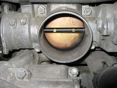
It isn't as complex as that, it actually has to do with the throttle valve in the throttle body restricting the air intake. Massive pumping losses exist trying to drag all the air through the restriction that is the throttle itself. If you have cold air, it is denser, so the engine needs less of it for a given power load, so it closes the throttle valve a bit more. If you have warm air, it is thinner, so the throttle opens more, less pumping loss, better efficiency. That's why a turbo engine works well, gives you a lot of power with compressed air when you need it, but when you don't need all that, it is an undersized engine that needs to open the throttle farther to keep up. The wider open throttle is key.
Diesels get good mileage because they don't have this pumping loss, they run wide open all the time, power is controlled by the amount of fuel being injected.
The key to the BSFC curve is if you use a small engine in a car, it is operating closer to its ideal island of efficiency, if you have an engine capable of lots of power, it is operating far outside it's peak efficiency at normal highway speeds.
I think too, if you do a warm air intake, it wouldn't slow you down when you need the power because you'll be pulling in so much air, it won't have time to get warmed up, so you'll still have close to peak power when you need it. Remember, 99.99% of the time, automotive engines are not using their rated output.
I have seen the enemy....
|
|
|
|
|
09-05-2012, 08:41 PM
|
#10 (permalink)
|
|
EcoModding Lurker
Join Date: Sep 2012
Location: United States
Posts: 9
Thanks: 0
Thanked 0 Times in 0 Posts
|
: D
I have never thought of it like that. I'm usually in for the most power and speed with just about everything I have owned. I do know through those experiences I always tried to achieve the thinnest throttle blade and shaft as possible for higher flow numbers. I was always interested in max flow at WOT and not how it acts under light load/partial acceleration. I see now how that can effect it. I see that with a HAI your engine will have less power. Therefore to make the same power to go the same speed, you have to open the throttle more, thereby decreasing plumbing losses. take and give like everything else I assume. As far as that is concerned I'm sticking with the stock intake that routes into the fender well. I'm afraid this tired thing will have trouble climbing hills. rather be safe than sorry.
Tomorrow I will finish under the hood and start installing my new hitch and fabricating the carrier basket. I picked up the hitch and all the steel tubing I will need throughout today. Just have to safe a few more bucks to get the aluminum sheeting to bring it all together. Tomorrow I'll start posting some fabrication pics and hopefully get some other people interested and commenting on this thread as well : )
|
|
|
|
|