I've been playing with this a bit more, I stumbled on this earlier then discounted it till today when I had a flashback,
Those words, over and over,
Body of rotation in free air, ground effect, mirror, then it clicked.
The template profile is to be used in radius, d is the diameter of the object, hence 1/2d is the radius, so side view is only relevant along the verticle centreline/spine of the vehicle and plan view relates to ground level (or maybe slightly above.
This all depends on where the focal point of the object cross section is considered to be, I haven't considered underflow in this exercise as my brain is too small.
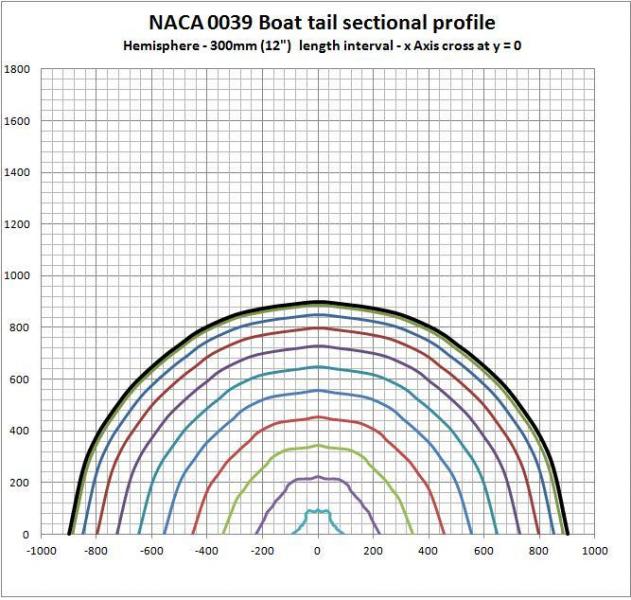
As I have been using the NACA 0039 equation, I re did the spreadsheet to take x & y coordinates, convert these to a radius measurement, put this through the equation for the airfoil at 300mm length intervals (this would be z in a 3d form), I then converted the calculated radius back to x & y coordinates and ploted them.
I first did a rough hemisphere to test the calculations, my co ordinates are not perfect, (hence the rough inner plots), but it does show regular increasing reduction as one would expect of half a teardrop form, chart below:

Then I punched in a set of coordinates for a square, to represent a basic vehicle profile, y crosses x at 0 (ground level), chart below:

What it does show is that the corners, being a diagonal profile are further from the focal point, hence their rate of taper is reduced, but the sides at ground level have the shortest length and the most aggressive change.
I am begining to doubt the narrowest dimension rule, this diagonal effect, for me seems to give some explanation why the whole square vehicle is so bad aerodynamically, because it is very difficult to get those corners together without seperation occuring.
I then raised the focal point to 300mm(12") above the ground to simulate something like my vehicle which has that ground clearance, as said before, numbers do not factor in any underflow air, chart below:

The pattern looks quite interesting as it lifts up off the ground towards the end, it starts to emulate the "Banana car" type forms with the tip starting to come up, I'd expect this to be even more exagerated if underflow air was factored in.
I'm sure there are many other things that come into play and no vehicle is completely square, but it does highlight the potential issues with corners being too aggressive in taper, and if looking for a vehicle to aero customize, it's worth paying more attention to the curvature of the frontal cross section, if it is really square, that will work against you more than if it is more circular.
I will go over formula's again tomorrow, but am pretty sure they are ok as per the hemisphere result.
Now I just got to figure out how to apply the form in this world, and wondering what other devils are lurking in the detail.