Go Back   EcoModder Forum > EcoModding > Aerodynamics
Register Now
 Register Now
 

Reply  Post New Thread
 
Submit Tools LinkBack Thread Tools
Old 01-28-2013, 01:01 AM   #461 (permalink)
Master EcoModder
 
Join Date: Feb 2012
Location: Australia
Posts: 355

The Truck - '02 Nissan GU Patrol ST
Thanks: 5
Thanked 76 Times in 50 Posts
Quote:
Originally Posted by ChazInMT View Post
Based on this statement, I now believe that the template application from the top view would fall somewhere in between my full width application and the base line in the center & mirrored application.


Bigger Versionto Oogle
Or


Bigger Version to Ponder

The baseline center thing just felt way too fast, but my using the full width of the car didn't seem to make sense either in that it seemed long. I think using the car height and applying it to the sides makes sense because the air will be closing in at the same relative speed thus reducing the chance of a pressure differential which would cause the air to spin.
I see it as the two limits, the larger dimension gives us the upper limit and the smaller dimension gives us the lower limit and the real world optimum may well lie somewhere in between.

I looked at some of the examples of Paul Jarays work back a few posts and analyzing the lines where the sides and top merge indicate even steeper angles, so I question whether there was seperation there or can we tolerate greater angles where we are bringing the two planes together?

  Reply With Quote
Alt Today
Popular topics

Other popular topics in this forum...

   
Old 01-28-2013, 03:48 AM   #462 (permalink)
Master EcoModder
 
freebeard's Avatar
 
Join Date: Aug 2012
Location: northwest of normal
Posts: 27,665
Thanks: 7,767
Thanked 8,575 Times in 7,061 Posts
ChazInMT -- Both your examples are conformist in elevation; but in plan, all of the bumper and fenders outboard the green line is non-conformist.

And this points up the problem architects run into working in plan and elevation. When you view this in 3D you find that the elevation profile only obtains *on the centerline of the vehicle*.
  Reply With Quote
Old 01-28-2013, 06:52 AM   #463 (permalink)
Master EcoModder
 
Join Date: Feb 2012
Location: Australia
Posts: 355

The Truck - '02 Nissan GU Patrol ST
Thanks: 5
Thanked 76 Times in 50 Posts
Not side view, nor plan, but radius.

I've been playing with this a bit more, I stumbled on this earlier then discounted it till today when I had a flashback,
Those words, over and over,
Body of rotation in free air, ground effect, mirror, then it clicked.
The template profile is to be used in radius, d is the diameter of the object, hence 1/2d is the radius, so side view is only relevant along the verticle centreline/spine of the vehicle and plan view relates to ground level (or maybe slightly above.
This all depends on where the focal point of the object cross section is considered to be, I haven't considered underflow in this exercise as my brain is too small.

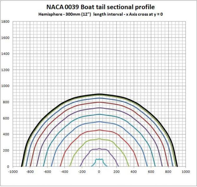
As I have been using the NACA 0039 equation, I re did the spreadsheet to take x & y coordinates, convert these to a radius measurement, put this through the equation for the airfoil at 300mm length intervals (this would be z in a 3d form), I then converted the calculated radius back to x & y coordinates and ploted them.

I first did a rough hemisphere to test the calculations, my co ordinates are not perfect, (hence the rough inner plots), but it does show regular increasing reduction as one would expect of half a teardrop form, chart below:


Then I punched in a set of coordinates for a square, to represent a basic vehicle profile, y crosses x at 0 (ground level), chart below:


What it does show is that the corners, being a diagonal profile are further from the focal point, hence their rate of taper is reduced, but the sides at ground level have the shortest length and the most aggressive change.

I am begining to doubt the narrowest dimension rule, this diagonal effect, for me seems to give some explanation why the whole square vehicle is so bad aerodynamically, because it is very difficult to get those corners together without seperation occuring.

I then raised the focal point to 300mm(12") above the ground to simulate something like my vehicle which has that ground clearance, as said before, numbers do not factor in any underflow air, chart below:


The pattern looks quite interesting as it lifts up off the ground towards the end, it starts to emulate the "Banana car" type forms with the tip starting to come up, I'd expect this to be even more exagerated if underflow air was factored in.

I'm sure there are many other things that come into play and no vehicle is completely square, but it does highlight the potential issues with corners being too aggressive in taper, and if looking for a vehicle to aero customize, it's worth paying more attention to the curvature of the frontal cross section, if it is really square, that will work against you more than if it is more circular.

I will go over formula's again tomorrow, but am pretty sure they are ok as per the hemisphere result.

Now I just got to figure out how to apply the form in this world, and wondering what other devils are lurking in the detail.
  Reply With Quote
The Following 4 Users Say Thank You to Tesla For This Useful Post:
aerohead (03-12-2016), betasniper (05-31-2013), freebeard (01-28-2013), hotrodfeguy (01-28-2013)
Old 01-28-2013, 12:29 PM   #464 (permalink)
EcoModding Lurker
 
Join Date: Apr 2010
Location: green bay WI
Posts: 52
Thanks: 7
Thanked 9 Times in 8 Posts
Now that is very interesting stuff!!! I could see that working BIG on a truck topper...
__________________
94 Geo Metro 52-56 MPG
06 Jetta TDI 46-48 MPG
  Reply With Quote
Old 01-28-2013, 03:17 PM   #465 (permalink)
Master EcoModder
 
freebeard's Avatar
 
Join Date: Aug 2012
Location: northwest of normal
Posts: 27,665
Thanks: 7,767
Thanked 8,575 Times in 7,061 Posts
That's an interesting result. Why the little 'ears' on the square?

I'm perplexed though; aren't you applying the airfoil profile to the selected cross-section? Why does the inverted triangle appear? Are you mapping air flow as well?

If you're up for it, try the Squircle. That's the one in the middle here:
  Reply With Quote
Old 01-28-2013, 04:04 PM   #466 (permalink)
Master EcoModder
 
Sven7's Avatar
 
Join Date: Aug 2011
Location: Warren, MI
Posts: 2,456

Boo Radley - '65 Ford F100
90 day: 13.28 mpg (US)
Thanks: 782
Thanked 668 Times in 410 Posts
Those beg to be cut out of sheet foam, glued together ala NeilBlanchard, and tuft tested.
__________________
He gave me a dollar. A blood-soaked dollar.
I cannot get the spot out but it's okay; It still works in the store
  Reply With Quote
Old 01-28-2013, 04:19 PM   #467 (permalink)
Master EcoModder
 
Join Date: Feb 2012
Location: Australia
Posts: 355

The Truck - '02 Nissan GU Patrol ST
Thanks: 5
Thanked 76 Times in 50 Posts
Quote:
Originally Posted by freebeard View Post
That's an interesting result. Why the little 'ears' on the square?

I'm perplexed though; aren't you applying the airfoil profile to the selected cross-section? Why does the inverted triangle appear? Are you mapping air flow as well?

If you're up for it, try the Squircle. That's the one in the middle here:
You may be talking about the start outline, that's just because I'm using a smooth line chart, so it throws some rounding in between points, this results in slightly distorted corners, it's a primative tool I'm using in the scheme of things.

Last edited by Tesla; 01-28-2013 at 07:41 PM..
  Reply With Quote
Old 01-28-2013, 04:41 PM   #468 (permalink)
Master EcoModder
 
Join Date: Feb 2012
Location: Australia
Posts: 355

The Truck - '02 Nissan GU Patrol ST
Thanks: 5
Thanked 76 Times in 50 Posts
Quote:
Originally Posted by Sven7 View Post
Those beg to be cut out of sheet foam, glued together ala NeilBlanchard, and tuft tested.
It's just an exersise at this stage to try to gain a deeper understanding of how it all works, but you did trigger an idea, if I'm not mistaken scale models also need to have scaled air speed, and I have clocked myself on the bicycle at 40km/hr, maybe I could strap something onto the front of the bike and go for a spin.
That way I may get some physical exercise as well.
  Reply With Quote
The Following User Says Thank You to Tesla For This Useful Post:
wyatt (01-28-2013)
Old 01-28-2013, 07:45 PM   #469 (permalink)
Master EcoModder
 
Join Date: Feb 2012
Location: Australia
Posts: 355

The Truck - '02 Nissan GU Patrol ST
Thanks: 5
Thanked 76 Times in 50 Posts
I really need to look a bit more at the underside and think about how that air interacts,
One of the things with all this Aero stuff is it is like the "Butterfly Effect" or "Feng Shui", if one minor aspect is changed the entire outcome can be flipped, funny stuff.
  Reply With Quote
Old 01-29-2013, 11:54 AM   #470 (permalink)
Recreation Engineer
 
KamperBob's Avatar
 
Join Date: Dec 2009
Location: Somewhere USA
Posts: 525

Black Stallion - '02 Toyota Tundra 4WD xCab

Half Pint - '06 Yamaha XT225
Thanks: 333
Thanked 138 Times in 103 Posts
Sections

I'm fascinated yet puzzled. This


looks like a series of "torpedo" upper-half cross sections (taken lengthwise from apex to rear) from the left side of this.


So then my brain wants this


to be "boxfish" sections from the right side. Where did my brain make a wrong turn please?

__________________
Recreation Engineer
  Reply With Quote
Reply  Post New Thread


Similar Threads
Thread Thread Starter Forum Replies Last Post
Maximum angle for boat tail? abcdpeterson Aerodynamics 80 11-03-2021 12:55 PM
Aerodynamic Streamlining Template Part-B aerohead Aerodynamics 8 05-31-2013 12:23 PM
LED Headlight captainslug DIY / How-to 82 11-15-2011 01:32 AM
Aerodynamic Streamlining Template: Part-A aerohead Aerodynamics 0 07-18-2009 02:37 PM
All items I scanned in the new product showcase dremd The Lounge 0 11-08-2008 04:14 PM


Powered by vBulletin® Version 3.8.11
Copyright ©2000 - 2024, vBulletin Solutions Inc.
Content Relevant URLs by vBSEO 3.5.2
All content copyright EcoModder.com