 10-05-2010, 06:06 PM
|
#1 (permalink)
|
|
Master EcoModder
Join Date: Jan 2008
Location: Sanger,Texas,U.S.A.
Posts: 16,543
Thanks: 24,520
Thanked 7,439 Times in 4,819 Posts
|
'Laminar' Aircraft and EcoModding
The topic of 'laminar' aircraft surfaces from time to time as pertaining to EcoModding and I thought it deserved its own thread.
I will let the guys with the PhDs speak for themselves as is practical,and will list sources for comments I make.
By numbering we may make quick references to a particular passage if need be.
(1) Aircraft aerodynamic drag is ruled by surface friction drag and designers are obsessed with laminar flow.Aerodynamacists engaged primarily in the design of the aircraft don't even concern themselves with flow separation as flow attachment is a premise of the computational tools they employ.(Theory of Wing Sections,Abbott and von Doenhoff,Ch.13.10.Pg.534,also Fluid Mechanics with Engineering Applications,Daugherty and Franzini,Pg.291.)
(2)Road vehicle aerodynamic drag is governed by flow separation and its attendent pressure drag.Surface drag is virtually insignificant.Above 4-MPH ( 7 Km/h ) a laminar boundary layer cannot exist and no amount of smoothing or polishing can improve the surface drag situation,except by limiting the wetted area to the 'crossover' point as is governed under the rules of streamlining.( Daugherty et al,CH.10,Example 10.2.pg. 288/Elementary Fluid Mechanics,Rouse,pg.248-249/Hucho pg. 54,215,and 535.)
(3) In aircraft,a laminar boundary layer is beneficial.In road vehicles a laminar boundary layer would be a detriment as a turbulent boundary layer can better maintain flow attachment against an adverse pressure gradient,reducing the all-important wake.Consider golf ball dimpling,dimple tape on aircraft,and turbulators ( vortex-generators ).( Daugherty pg.294/Rouse CH.8,Pg.234,246,and PLATE XVI.)
(4) For both 'laminar' and turbulent' boundary layers the flow outside these in the free stream 'inviscid'/'ideal fluid' layers is laminar,unless 'stall' or 'separation' is occurring.( Daugherty,pg. 280.)
(5) 'Laminar' aircraft are designed for 'flight conditions' and 'flight values of Reynolds number' far away from the ground with free air above and below,lower air density,and freedom from turbulence.( Daugherty pg.541 TABLE A.3a,IACO standard atmosphere.)
(6) "the flow around actual road vehicles is mainly turbulent.... random eddy fluctuations..... unsteady macro-structures which may be present." ( Hucho,CH.13.9,pg. 528,pg. 534.)
(7) "seemingly insignificant surface details can trigger major changes in the overall vehicle flow field." ( Hucho,Ch.13,pg. 529.)
(8) In ground proximity the transition from laminar to turbulent boundary layer occurs at Reynolds number = 500,000,which say,for a Toyota Prius will take place below 4-MPH ( 7 km/h ).( Daugherty/Hucho ).
(9) Describing an aircraft as 'laminar' can be a misnomer,as unless suction is provided along the chord,the laminar boundary layer will only last up to approximately the first location of minimum pressure,separate,then re-attach at flight Reynolds numbers as a turbulent boundary layer extending to the trailing edge.
*********** "if the airstream is turbulent..... transition from laminar to turbulent flow may occur anywhere upstream of the calculated laminar separation point." ( Abbott et al ).
(10) Abbott et al: Ch.1 pg. 28,"APPLICABILITY of SECTION DATA"
----- "simplifying assumptions"
---- " Strict compliance with this assumption would require 2-dimensional flow"( road vehicles operate within 3-D flow,hence the Navier-Stokes equations of 3-D in spherical coordinate system to solve,especially their wakes ) ".....no lift along the span..... no crossflows in the boundary layer.... (otherwise) wing characteristics may depart seriously from the calculated ones........... conditions are obviously not satisfied near the wing tips,near the extremities of partial span flaps or deflected ailerons,near cutouts and large fillets,or if the wing is partially stalled.Since the assumed conditions are not satisfied near the wing tips,it is obvious that section data are not applicable to wings of low aspect ratio.In fact,an entirely different theory applies to wings of very low aspect ratio."
(11) Abbott cites Reference#57,Jones,Robert T.: Properties of Low-aspect Ratio Pointed Wings at Speeds below and above the Speed of Sound,NACA TN No. 1032,1946.).
(12) Example:
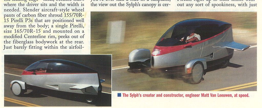
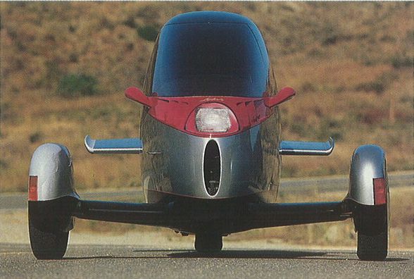
Aerospace engineer,Matt Van Leeuwan designed his 3-wheeled "Sylph" around the architecture of a NACA 66-Series airfoil of 6% thickness.
From Abbott,this wing section demonstrates a drag minimum of Cd 0.003 'clean',and Cd 0.0085'rough'.
NOTE: The airfoil Cd is based on surface drag of the wings planform area ( both sides ),a function of chord length and a given span.As Patrick was kind enough to point out,to convert to frontal area Cd as used in road vehicle aerodynamics,the surface drag coefficient is multiplied by the inverse of the airfoils thickness percentage,which in the case of Sylph would be 1/0.06=16.666 X 0.003 = Cd 0.05.
Section thickness for this airfoil occurs at 45% of chord behind the leading edge.
Allowing the shoulder room of a Piper Cub,Sylph would require a length of over 33-feet to respect the NACA thickness ratio.
Also,as Abbott points out,Sylph might embody two 'wingtips' of the 66-Series section joined together but it can never satisfy the criteria for section data "APPLICABILITY".
Additionally,the Sylph is operating in ground proximity,which Jaray found to double a body's drag,as well as introducing turbulence effects as mentioned by Hucho.
Consequently,Sylph registered only Cd 0.103 at California Institute of Technology's Guggenheim Aeronautical Laboratory wind tunnel ( a 206 % drag increase over the 66-Series section at flight value ).
(13) I hope the above discussion will illustrate that while 'laminar' aircraft are to be highly desired as aircraft,their attributes may offer little when in the context of a road vehicle operating in ground proximity,in turbulent air,and 3-Dimensional flow; none of the parameters for which aircraft designs are executed,nor in which their efficiency relies.
Last edited by aerohead; 10-09-2010 at 12:29 PM..
Reason: correct data error at #12
|
|
|

|
|
The Following 3 Users Say Thank You to aerohead For This Useful Post:
|
|
 Today Today
|
|
|
|
 Other popular topics in this forum...
|
|
|
|
|
10-05-2010, 11:22 PM
|
#2 (permalink)
|
|
Master EcoModder
Join Date: Dec 2008
Location: Southern WI
Posts: 829
Thanks: 101
Thanked 563 Times in 191 Posts
|
Hi Phil,
So does the Sylph shape have an advantage over the highly touted Morelli shape?
Jim.
|
|
|
|
|
10-06-2010, 09:59 AM
|
#3 (permalink)
|
|
Master EcoModder
Join Date: Apr 2008
Location: Northern Florida, USA
Posts: 510
Thanks: 27
Thanked 96 Times in 70 Posts
|
WRT #12):
Aircraft wing section coefficients are calculated based on the planform area, not the frontal area. So for a 6% section, you have to multiply the coefficent by 16.67 (100/6): 0.003 x 16.67 = 0.05 Cd based on frontal area. So the 0.103 found in the CalTech wind tunnel is only a 106% increase. For comparison, what were the Cds of the other bikes in the competition?
The GM Sunraycer was based on a 63-series wing section and AeroVironment claims that laminar flow was achieved up to the 30% chord maximum thickness.
|
|
|
|
|
The Following User Says Thank You to Patrick For This Useful Post:
|
|
|
10-07-2010, 06:06 PM
|
#4 (permalink)
|
|
Master EcoModder
Join Date: Jan 2008
Location: Sanger,Texas,U.S.A.
Posts: 16,543
Thanks: 24,520
Thanked 7,439 Times in 4,819 Posts
|
Sylph/Morelli
Quote:
Originally Posted by 3-Wheeler

Hi Phil,
So does the Sylph shape have an advantage over the highly touted Morelli shape?
Jim.
|
Jim,I'm hoping Neil Blanchard can help out on this one.I may be incorrect,but I thought that Aptera was using the Morelli form.
Under the X-Prize protocols all the cars were to be coastdown tested to ascertain both Cd and Rolling Force coefficient for dyno calibration.
If that information is in the public domain,then we may have access to actual ground proximity Cd values for that shape.
The we could make an appraisal of the two forms.If the Cal Tech numbers are 'hard.' |
|
|
|
|
10-07-2010, 06:16 PM
|
#5 (permalink)
|
|
Master EcoModder
Join Date: Jan 2008
Location: Sanger,Texas,U.S.A.
Posts: 16,543
Thanks: 24,520
Thanked 7,439 Times in 4,819 Posts
|
based
Quote:
Originally Posted by Patrick
WRT #12):
Aircraft wing section coefficients are calculated based on the planform area, not the frontal area. So for a 6% section, you have to multiply the coefficent by 16.67 (100/6): 0.003 x 16.67 = 0.05 Cd based on frontal area. So the 0.103 found in the CalTech wind tunnel is only a 106% increase. For comparison, what were the Cds of the other bikes in the competition?
The GM Sunraycer was based on a 63-series wing section and AeroVironment claims that laminar flow was achieved up to the 30% chord maximum thickness.
|
Thanks Patrick!,I seem to be falling into the very traps I'm trying to keep everyone out of.Yes,a big heaping bowl of stupid can be found being served up at the Knox household!
As to the other bikes,it was presumed that they all shared virtually the same Cd.Not much of an answer I know.
I plan to go back next year,and not on the closing day,so perhaps I can glean more info and query more teams.
I thought Sunraycer's overall flow would be laminar in its entirety.I've seen wind tunnel smoke-flow images of similar cars and there is no perceptible separation the whole length,smoke,quite literally clawing the aft-body surface.Beautiful! |
|
|
|
|
10-09-2010, 12:35 PM
|
#6 (permalink)
|
|
Master EcoModder
Join Date: Jan 2008
Location: Sanger,Texas,U.S.A.
Posts: 16,543
Thanks: 24,520
Thanked 7,439 Times in 4,819 Posts
|
Data correction @ #12
I just edited comment # 12, as Patrick was sharp enough to catch the intellectual pit I'd fallen into.If you read the original post you will see a significant difference between the planform surface area drag coefficient,and when it is converted to a frontal area-based Cd.
Thanks again to Patrick's eagle-eye!
|
|
|
|
|
10-13-2010, 06:38 PM
|
#7 (permalink)
|
|
Master EcoModder
Join Date: Jan 2008
Location: Sanger,Texas,U.S.A.
Posts: 16,543
Thanks: 24,520
Thanked 7,439 Times in 4,819 Posts
|
Laminar B-L caveats
Quote:
Originally Posted by Patrick
WRT #12):
Aircraft wing section coefficients are calculated based on the planform area, not the frontal area. So for a 6% section, you have to multiply the coefficent by 16.67 (100/6): 0.003 x 16.67 = 0.05 Cd based on frontal area. So the 0.103 found in the CalTech wind tunnel is only a 106% increase. For comparison, what were the Cds of the other bikes in the competition?
The GM Sunraycer was based on a 63-series wing section and AeroVironment claims that laminar flow was achieved up to the 30% chord maximum thickness.
|
Patrick,I spent some time with my books and believe I understand the situation with Sunraycer which was described by Bart.
---------------------------------------------------------------------------
With a 'flat plate' the transition from laminar to turbulent boundary layer would occur around 500,000.
--------------------------------------------------------------------------
For a smooth body,if the pressure is decreasing in the direction of flow ( which is what is occurs at the front of Sunraycer as air accelerates towards the position of maximum cross-section ),this will have a stabilizing effect on a laminar boundary layer up to the first position of minimum pressure,which in the case of Sunraycer would be about 30 % of body length.
Then after the transition,the turbulent boundary layer helps hold the flow against the aft-body all the way to the trailing edge.
When looking at tables I had to be aware of if whether the author was discussing flat plates parallel to flow,perpendicular to flow,or bluff bodies in 3-D flow.
Also,when looking at wing performance,the following were mentioned as criteria which could affect:
* thickness ratio
* area
* aspect ratio
* taper ratio
* aerodynamic twist
* angle of sweepback
* section lift-curve slope
* effective lift-curve slope
* Jones edge-velocity factor
* section-moment coefficient about the aerodynamic center
* chord at any spanwise station
* air density
* air turbulence level
* air velocity/Mach number/local Mach number
*angle of attack
* roll
* side slip
* surface roughness
* camber
* vibration/damping/amplification
* unsteadiness
* frequencies/harmonics
* pitching moments
* interference
* induced drag
* waviness
* slipstream
* wing loading
* wing root
* wing tip
* slats
* flaps
* slots
* slits
* aileron
* blowing
* suction
* turbulators
* dive brakes
* compressibility
My head hurts! |
|
|
|
|
The Following 2 Users Say Thank You to aerohead For This Useful Post:
|
|
|
11-09-2015, 06:48 PM
|
#8 (permalink)
|
|
Master EcoModder
Join Date: Jan 2008
Location: Sanger,Texas,U.S.A.
Posts: 16,543
Thanks: 24,520
Thanked 7,439 Times in 4,819 Posts
|
Sylph photos
Finally!,some images.At 1/4-scale in the Cal Tech GALCIT wind tunnel,Cd 0.103
__________________
Photobucket album: http://s1271.photobucket.com/albums/jj622/aerohead2/
|
|
|
|
|
The Following 4 Users Say Thank You to aerohead For This Useful Post:
|
|
|
12-05-2020, 02:00 PM
|
#9 (permalink)
|
|
Ultimate Fail
Join Date: Feb 2008
Location: Austin,Texas
Posts: 3,585
Thanks: 2,872
Thanked 1,121 Times in 679 Posts
|
What is this an example of ?
It appears as if the boundary layer is attached all along the sides of the vehicle, and becomes seperated even for these rivets, which protrude pehaps 4 millimeteres.
I was under the impression that airflow remains turbulent and unattached along the skin of a vehicle.
Not being doubtful, but rather inquisitive what I am seeing here.
( After looking at the photo again, I realize that this area would be in turbulent flow anyway, because the wheel is directly in front of this area .)
Last edited by Cd; 12-05-2020 at 02:05 PM..
|
|
|
|
|
12-05-2020, 03:24 PM
|
#10 (permalink)
|
|
Banned
Join Date: Nov 2017
Location: Australia
Posts: 2,060
Thanks: 107
Thanked 1,608 Times in 1,137 Posts
|
Quote:
Originally Posted by Cd
What is this an example of ?
It appears as if the boundary layer is attached all along the sides of the vehicle, and becomes seperated even for these rivets, which protrude pehaps 4 millimeteres.
I was under the impression that airflow remains turbulent and unattached along the skin of a vehicle.
Not being doubtful, but rather inquisitive what I am seeing here.
( After looking at the photo again, I realize that this area would be in turbulent flow anyway, because the wheel is directly in front of this area .)
|
Unfortunately this thread goes for massive complexity where there is no need to. Forget laminar boundary layer flow: as is (correctly) stated above, there is basically none over a normal car. Instead, where there is attached flow, it is in the form of a turbulent boundary layer.
In normal road vehicles, we really need to think only about two things:
1) Whether the flow is attached (airflow guided by the shape of the vehicle) or separated (airflow not guided by the shape of the vehicle).
2) Where it is attached, the thickness of the boundary layer (with the boundary layer being where the flow is slower than the freestream), and with boundary layer thickness growing the longer the flow is attached.
Looking at the pics, my guess is that the rivets are shielding the bodywork from dirt being thrown up by the wheel, and/or the truck has brushed against something and again the rivets have protected the bodywork behind them.
|
|
|
|
|
The Following User Says Thank You to JulianEdgar For This Useful Post:
|
|
|


