06-02-2012, 01:01 PM
|
#1 (permalink)
|
|
EcoModding Lurker
Join Date: Jun 2012
Location: New York
Posts: 3
Thanks: 0
Thanked 0 Times in 0 Posts
|
The most aerodynamic shape possible
Is there anything that is more aerodynamic than the airfoil shape?
does something that perfectly flat that runs horizontally (something like the shape of a CD) more aero dynamic?
|
|
|

|
 Today Today
|
|
|
|
 Other popular topics in this forum...
|
|
|
|
|
06-02-2012, 02:07 PM
|
#2 (permalink)
|
|
Master EcoModder
Join Date: Jan 2008
Location: Sanger,Texas,U.S.A.
Posts: 16,330
Thanks: 24,452
Thanked 7,393 Times in 4,788 Posts
|
context
Quote:
Originally Posted by taper41

Is there anything that is more aerodynamic than the airfoil shape?
does something that perfectly flat that runs horizontally (something like the shape of a CD) more aero dynamic?
|
*'aerodynamic' has no real meaning until a context is applied.
* trees are aerodynamic,so are mountains,fences,lungs,vocal chords,trumpets,........................... you get the picture.
*If you mean 'lower drag' than something else,then probably not.
*Investigators have found that a thickness at the leading edge,and then gentle taper to a point produces the lowest drag.
*For 2-dimensional flow,a symmetrical wing section of chord/thickness ratio = 3.94:1 produces the lowest drag.
*For 3-dimensional flow in free flight,a streamline body of revolution of length/diameter = 2.1:1-to-approx. 3:1 has demonstrated the lowest drag.
*For 3-dimensional flow in ground proximity,a 'half-body' of length/height = 5:1 has demonstrated the lowest drag,given the peculiarities of bluff-body flow in ground-effect.
--------------------------------------------------------------------------
If any of these structures are shortened,they experience a drag increase due to separation-induced pressure drag.
If any of these structures are lengthened,they undergo a drag increase due to increased skin-friction drag.
--------------------------------------------------------------------------
There are some 'laminar' forms investigated for submarines and airships which as of the mid-1990s had not evolved beyond the CFD stage.Any spanwise flow on these forms triggers an immediate transition to turbulent boundary layer and all benefits are lost.
For automobiles these forms offer no gains,as the 'source flow' itself is turbulent once to 20 mph and again,the transition to TBL is immediate. |
|
|
|
|
The Following User Says Thank You to aerohead For This Useful Post:
|
|
|
06-02-2012, 07:28 PM
|
#3 (permalink)
|
|
Master EcoModder
Join Date: Jul 2011
Location: Ann Arbor, Michigan
Posts: 4,188
Thanks: 132
Thanked 2,812 Times in 1,974 Posts
|
Nice post Aerohead, I got something new out of it, or just maybe it's starting to all sink in.
Taper41, if you have a lot of time to kill, start at page one of the thread below.
http://ecomodder.com/forum/showthrea...-c-9287-9.html
From page-9 the template I like to use:
The idea car? (Page-7) Aerohead did this one

__________________
George
Architect, Artist and Designer of Objects
2012 Infiniti G37X Coupe
1977 Porsche 911s Targa
1998 Chevy S-10 Pick-Up truck
1989 Scat II HP Hovercraft
You cannot sell aerodynamics in a can............
|
|
|
|
|
06-03-2012, 06:27 PM
|
#4 (permalink)
|
|
Master EcoModder
Join Date: Dec 2011
Location: Boise Idaho
Posts: 842
Thanks: 39
Thanked 89 Times in 69 Posts
|
Hey Aero,
if we take the car in the picture above, and start right above the back window.
then we angle down at 20 degrees. Will we end up with almost the same aero, but have a much shorter car?
|
|
|
|
|
06-03-2012, 10:35 PM
|
#5 (permalink)
|
|
Master EcoModder
Join Date: Jul 2011
Location: Ann Arbor, Michigan
Posts: 4,188
Thanks: 132
Thanked 2,812 Times in 1,974 Posts
|
No, as far as I understand it (but I'm not Aerohead).
I think thats the point of the 5:1 comment in close proximity to the ground, verses the 3:1 of "free air".
__________________
George
Architect, Artist and Designer of Objects
2012 Infiniti G37X Coupe
1977 Porsche 911s Targa
1998 Chevy S-10 Pick-Up truck
1989 Scat II HP Hovercraft
You cannot sell aerodynamics in a can............
|
|
|
|
|
06-04-2012, 09:13 AM
|
#6 (permalink)
|
|
Master EcoModder
Join Date: May 2008
Location: Maynard, MA Eaarth
Posts: 7,908
Thanks: 3,475
Thanked 2,952 Times in 1,845 Posts
|
A car is three dimensional, so the 2D profile of an airfoil is only part of the picture. the sides should be tapered -- in fact, the sides can be tapered about as much as the top, and since the taper happens on both sides, this would shortened the length quite a bit, and end up forming a "fish tail".
Look at the Edison2 VLC (Very Light Car) for an example of this. The VLC was tested in the GM wind tunnel and got a Cd (using the older SAE formulas) of 0.145; so this is comparable with most of the Cd numbers we have used here on EM. The newer SAE formulas gave a Cd of 0.164. The VLC has a relatively "pointy" front end and outboard wheels, so if you apply the above profile to a chassis that has enclosed wheels (and a much narrower rear wheel track), then the Cd could likely be even lower.
|
|
|
|
|
06-04-2012, 09:29 AM
|
#7 (permalink)
|
|
Master EcoModder
Join Date: Jul 2011
Location: Ann Arbor, Michigan
Posts: 4,188
Thanks: 132
Thanked 2,812 Times in 1,974 Posts
|
Quote:
Originally Posted by NeilBlanchard
A car is three dimensional, so the 2D profile of an airfoil is only part of the picture.
|
Correct, here is one of the other useful images from page-1 of the C-template thread:
http://ecomodder.com/forum/showthrea...rt-c-9287.html

__________________
George
Architect, Artist and Designer of Objects
2012 Infiniti G37X Coupe
1977 Porsche 911s Targa
1998 Chevy S-10 Pick-Up truck
1989 Scat II HP Hovercraft
You cannot sell aerodynamics in a can............
|
|
|
|
|
06-04-2012, 06:52 PM
|
#8 (permalink)
|
|
Master EcoModder
Join Date: Jan 2008
Location: Sanger,Texas,U.S.A.
Posts: 16,330
Thanks: 24,452
Thanked 7,393 Times in 4,788 Posts
|
20 degrees
Quote:
Originally Posted by drmiller100
Hey Aero,
if we take the car in the picture above, and start right above the back window.
then we angle down at 20 degrees. Will we end up with almost the same aero, but have a much shorter car?
|
I'd hoped to have Walter Lay's work posted by now.Hucho touches on it but kind of butchers what he did.
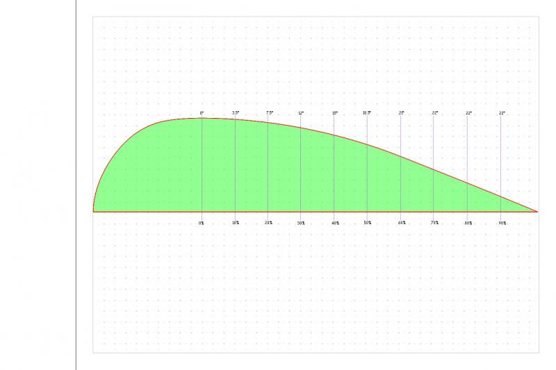
Lay did not follow the 'Template' per se,but he did pull the roofline down gently for the 1st 15% of the 'Template' to a 18-degree angle,and then held that constant slope out to 88% of the 'Template.'
He bent the sides in gently,starting at 10% of 'Template',into a 12-degree inward slope and held that constant 12-degrees all the way to 88%'Template',where the body ended in a point.
Lay published Cd 0.12 for the model.
Four of his models were reported at Cd 0.12.They all had 100% tails.All the tails were identical.The models only varied at the front.
--------------------------------------------------------------------------
His models end at 88% of 'Template' with Cd 0.12 for a simple model with wheels.
I'm representing Cd 0.13 at the same length and I mean to be conservative in light of the wheel fairings.
Lay's tail would 'tin-can' and would require internal bracing across all spans,like Lindbergh's Ryan Flyer or Beech Bonanza.
The 'Template',being ovoid,is among the strongest structures known,would require no bracing and can be made the lightest of all,which is a non-aerodynamic driver for its choice.Of course,it's also the most complicated to fabricate as there isn't a straight line on it anywhere.
-------------------------------------------------------------------------
20-degrees might work.It did okay on the VW and I think NASA stayed around 20-degrees with their Ford van.
Lay's design would be a no-brainer,it's a little more conservative,but he got pretty tasty numbers.With cooling system mods,skirts,MOONs,and wheel fairings,I don't see any reason why the gas pumps wouldn't be suicidal towards it. |
|
|
|
|
06-04-2012, 06:54 PM
|
#9 (permalink)
|
|
Master EcoModder
Join Date: Jan 2008
Location: Sanger,Texas,U.S.A.
Posts: 16,330
Thanks: 24,452
Thanked 7,393 Times in 4,788 Posts
|
2 other views
Quote:
Originally Posted by NeilBlanchard
A car is three dimensional, so the 2D profile of an airfoil is only part of the picture. the sides should be tapered -- in fact, the sides can be tapered about as much as the top, and since the taper happens on both sides, this would shortened the length quite a bit, and end up forming a "fish tail".
Look at the Edison2 VLC (Very Light Car) for an example of this. The VLC was tested in the GM wind tunnel and got a Cd (using the older SAE formulas) of 0.145; so this is comparable with most of the Cd numbers we have used here on EM. The newer SAE formulas gave a Cd of 0.164. The VLC has a relatively "pointy" front end and outboard wheels, so if you apply the above profile to a chassis that has enclosed wheels (and a much narrower rear wheel track), then the Cd could likely be even lower.
|
Neil,I did post a front elevation and plan-view of the 'Template' but I had to do it with a separate thread.I'd have to dig back to find it.
-------------------------------------------------------------------------
'new images for 'template' ' is the other thread where the other views are.These were just drawings that were in the works.When you see Jaray's,Lay's,Koenig-Fachsenfeld/Kamm,and Korff's plan-tapers,you'll see where I was going.
Last edited by aerohead; 06-04-2012 at 07:11 PM..
Reason: add data
|
|
|
|
|
06-04-2012, 07:05 PM
|
#10 (permalink)
|
|
Master EcoModder
Join Date: Jan 2008
Location: Sanger,Texas,U.S.A.
Posts: 16,330
Thanks: 24,452
Thanked 7,393 Times in 4,788 Posts
|
think
Quote:
Originally Posted by kach22i
No, as far as I understand it (but I'm not Aerohead).
I think thats the point of the 5:1 comment in close proximity to the ground, verses the 3:1 of "free air".
|
Yes,if the 'Template' is placed over a mirror,and you look at it and its reflection,you see that its L/H=5,and L/D=2.5.
Without wheels,in ground effect it is Cd 0.08.
Without wheels,in free flight,it is Cd 0.04.
With wheels,and in ground effect,it would be on the order of Cd 0.12+,depending on the wheels/tires.
With comprehensive wheel fairings,as seen in record cars and solar racers,the Cd would go below 0.12.
The 2.5:1 L/D is about the shortest ratio which still respects Mair's 22-degree back-slope limit for attached boundary layer flow.
|
|
|
|
|