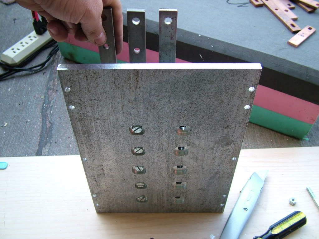
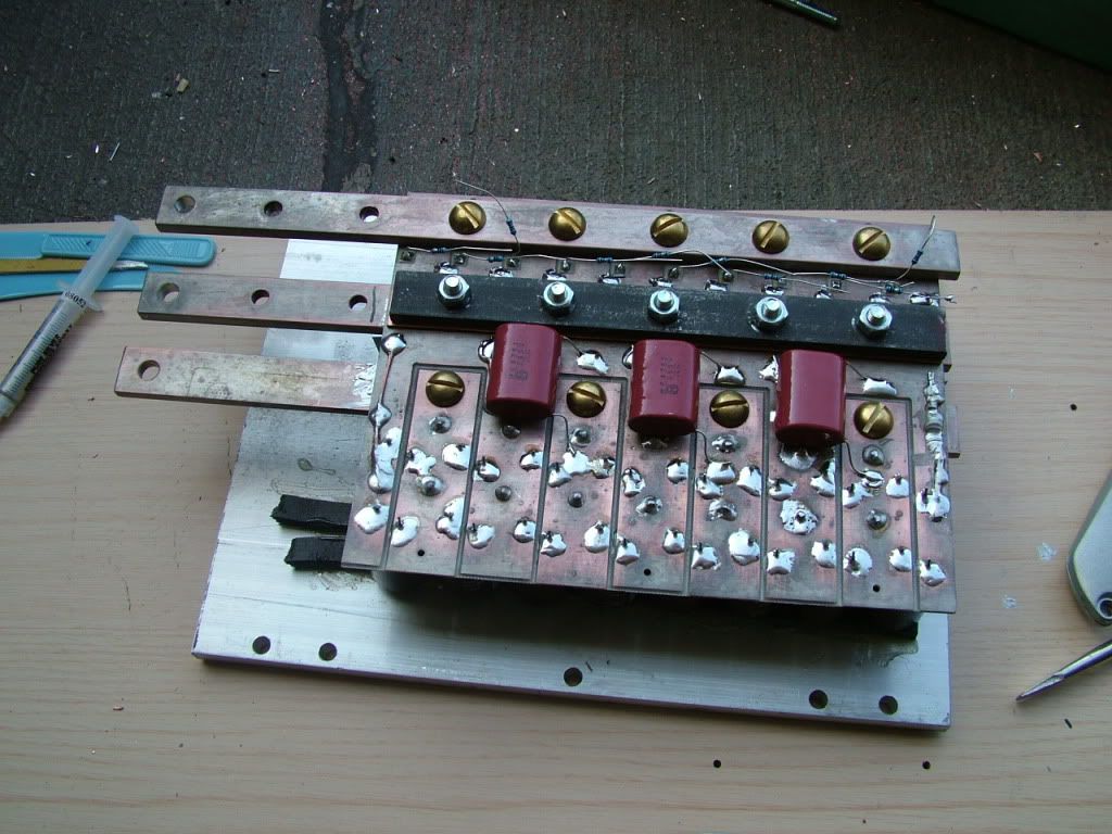
See those 2 indents that run horizontally across the mosfet clips? (it's hard to explain). Basically the clips clamp the mosfets down in two spots. The upper middle and lower middle, with quite a bit of force (like 15 or 20 pounds I think). Clamping through the hole just puts pressure at the top of the mosfets/diodes. Maybe that's fine, but another benefit is that you don't have to align them so the diodes and mosfets holes line up when you use clips. Later on, I'll probably use 12 diodes and 10 mosfets, since the mosfets can handle more current than the diodes. That would make alignment very difficult if I wanted to just have the diodes closer together.
The Lexan case is NO MORE! Well, maybe the endcaps for this go around. I don't know. hehe. Hondo made some enclosures out of pretty fancy heavy duty aluminum for free! and he even shipped them and they are on their way!
I'm learning some tricks to avoid some really really annoying things that can happen along the way. Holy cow.
Here's some pictures of the progress (I took 43 pictures this time, and 59 earlier today, so check out photobucket if you want to see all the details! MPaulHolmes on Photobucket):
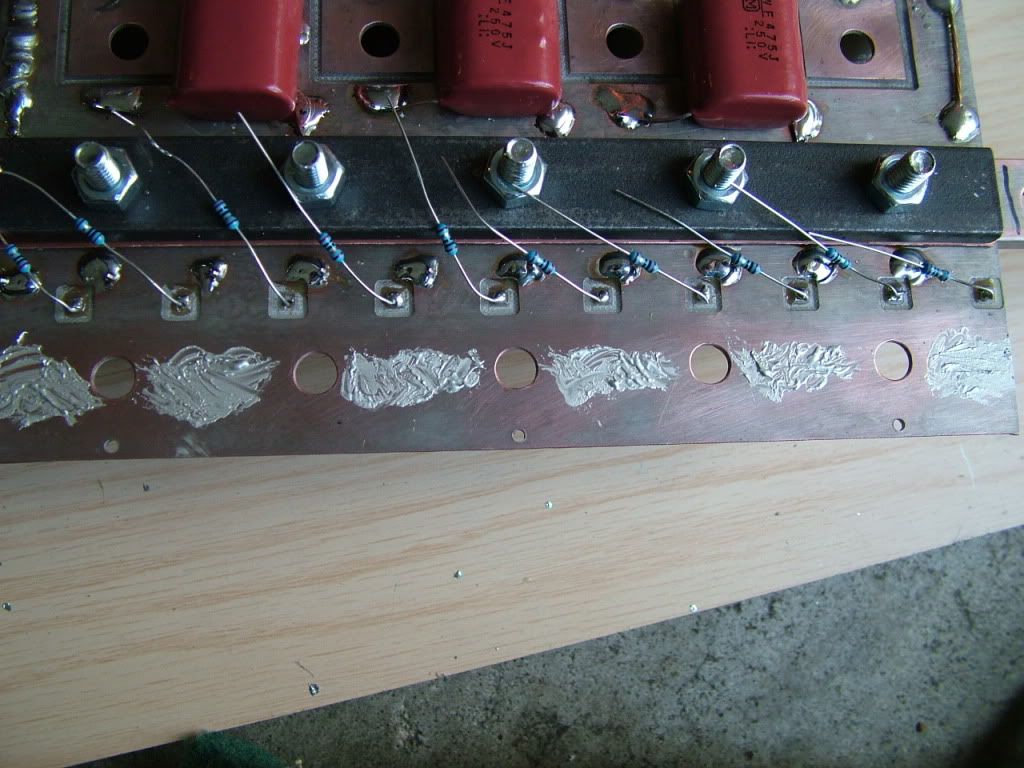
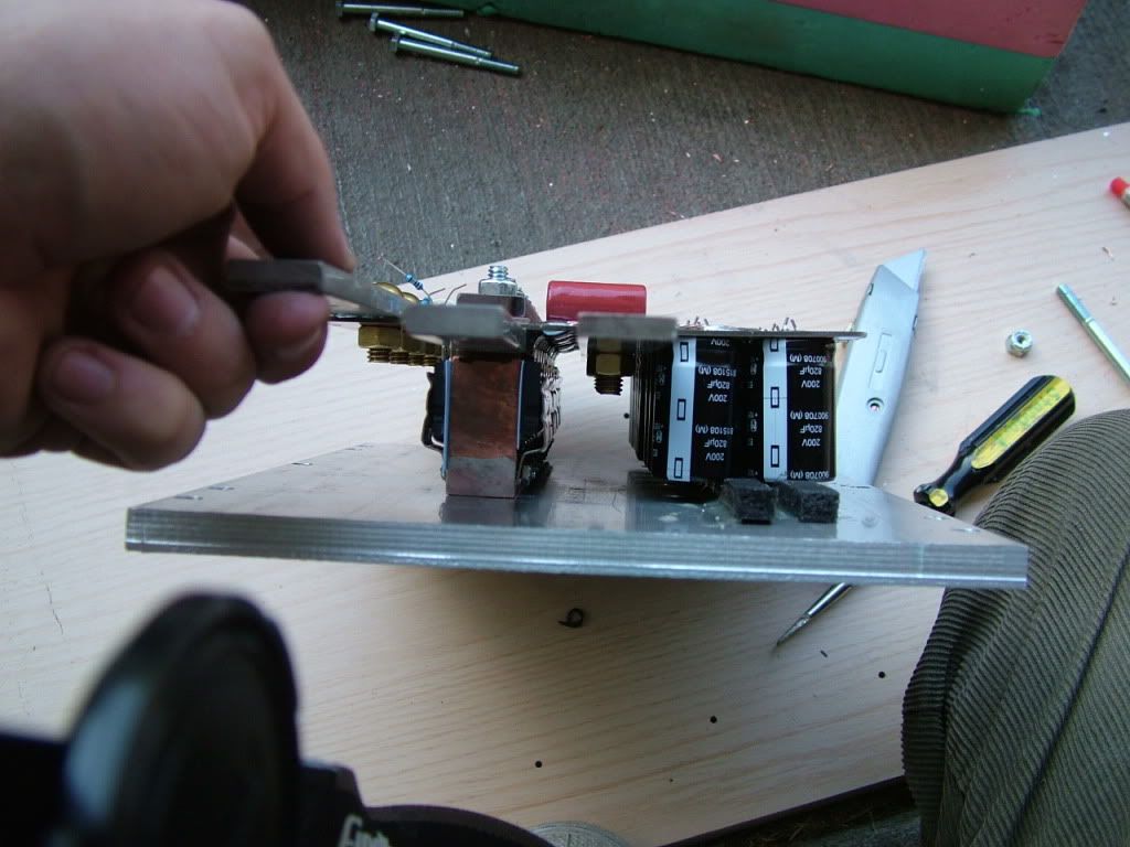
This idea came to me as I was working on it. IN the next version I can get that B- bar even closer. Almost right underneath the mosfets! It shrinks the necessary space down for the PCBby about 0.25", and makes the MOSFETS/DIODES/CAPACITOR loop shorter! :
Joe, avert your eyes. below is my mistake. I'm sorry.

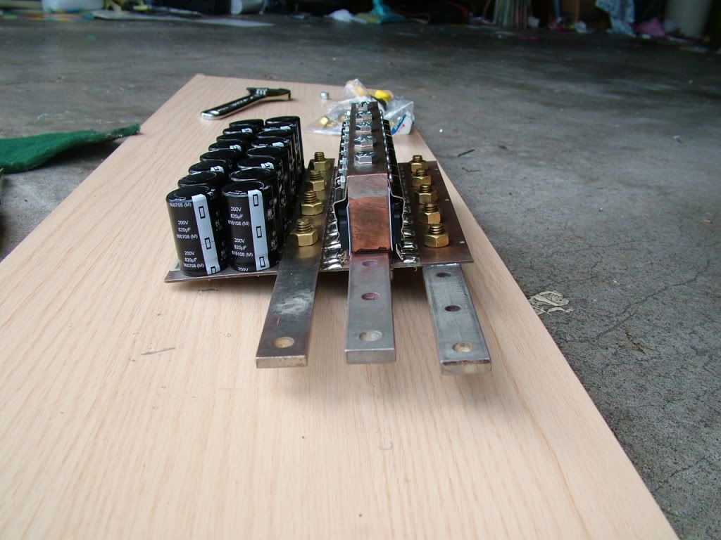
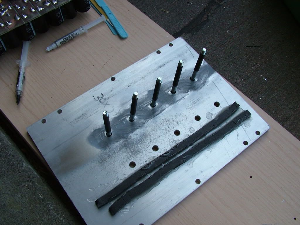
See those bolts!? I turned them into screws. hehe. I'm so sneaky sometimes! I can hardly stand it!