I programmed the microcontroller for the first time tonight! I made up a basic circuit for in-system programming. I turned on an LED, then I turned on another LED! hahaha. There were several irritating things that happened along the way, but I digress...
I got the encoder installed on the motor. I had to mill a flat plate and JB weld it onto the motor, so there would be a nice surface to stick the encoder. It's perfectly centered, since I ordered a centering tool. I took pictures, but the camera just ran out of batteries, so they are charging right now.
EDIT: THEY ARE DONE CHARGING!
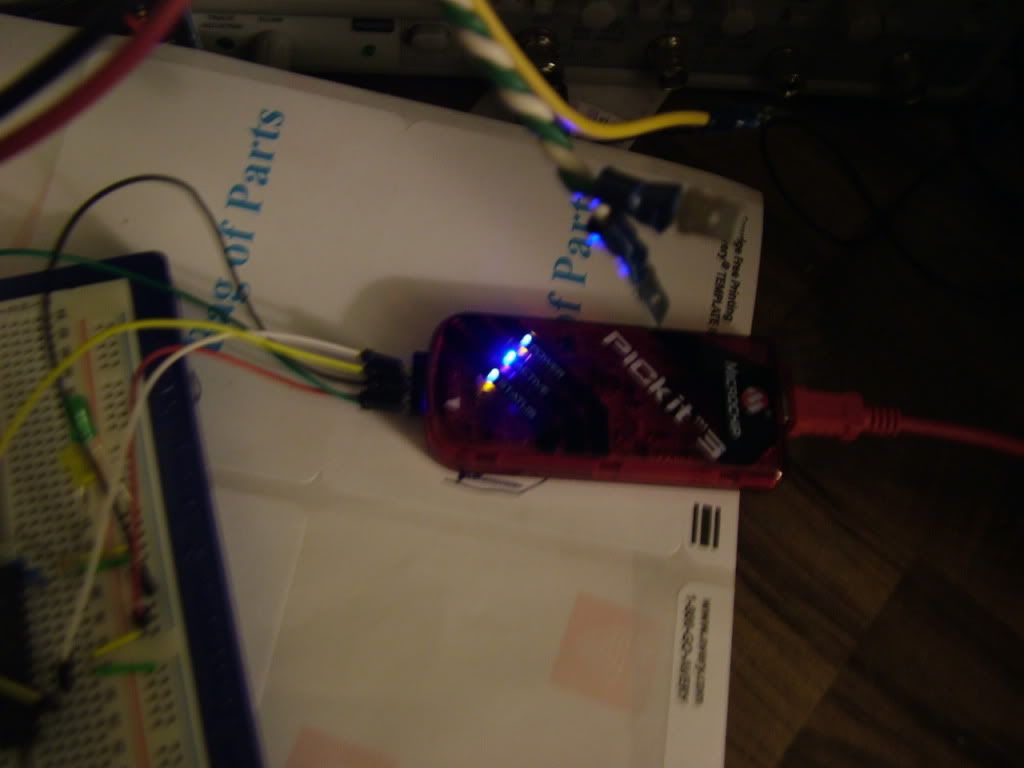
PicKit3 in action! Thank you sawickm!!!!!

Here's the test circuit for in-system programming!

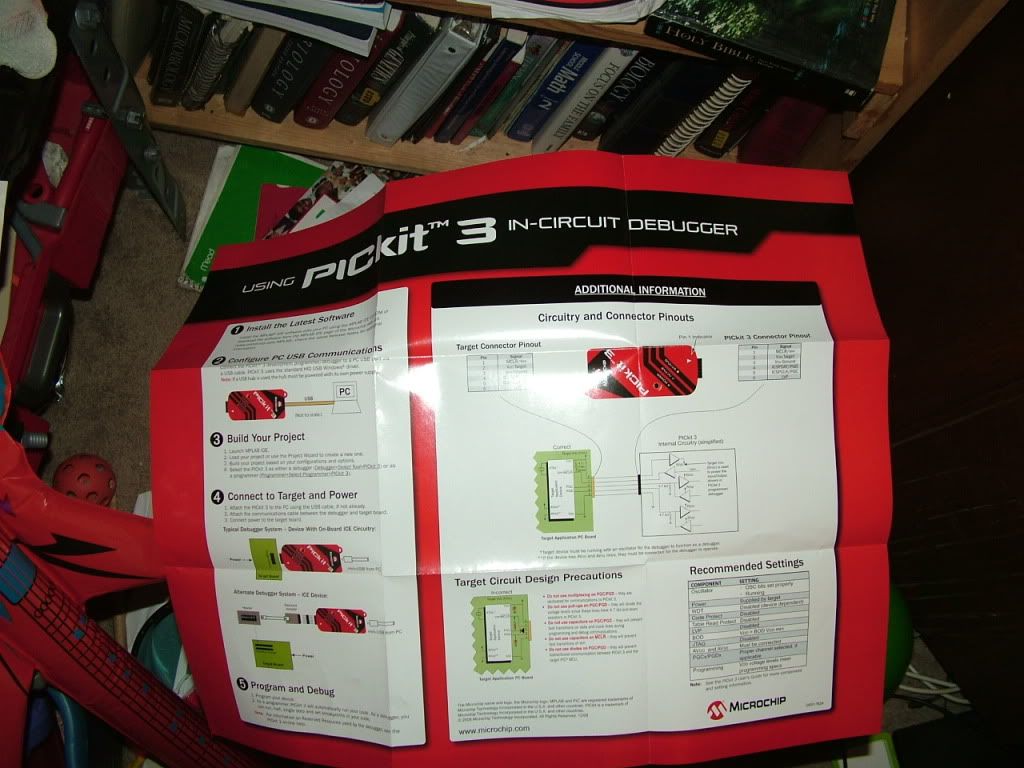
So, how do you program this dang chip anyway? Follow these directions!

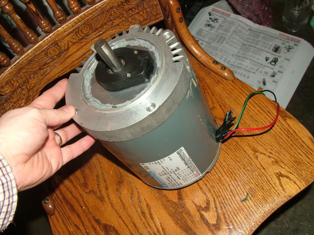
Here's the 3 phase AC test motor. Notice the encoder mounted on the motor shaft. It has 512 pulses per revolution:

Next I'm going to get the A/D channels working, and then the pwm working. Then all 6 of them working, and then drive 6 LEDs at the same time (like a 3 phase bridge), and then hook it up to the motor!
I've been deriving the clarke and park transformations to make sure I understand what is going on. It's not bad at all now! I understand! In fact, I found a mistake in the Application Note AN908 that everyone always talks about. They have the wrong transformation for Park! The most important part was wrong! I had actually used that transformation when I used to make really stupid video games. It's a 2D rotation. I'll add the pictures later.
Jack Bauer is using 1200v 1000amp IGBTs! If I can get 6 of those for a 3 phase bridge, that would be some crazy crazy power. Profoundly disturbing power.