Here's the driver board I'm planning on using. 2 drivers should be good for up to 20 mosfets, but I'm just going to try 14 for my prototype. That's about 71 or 72 amps per device for 1000 amps. I'm just hoping that it could do that for like 10 seconds. Enough to get up to speed in stop and go traffic, and do burnouts.
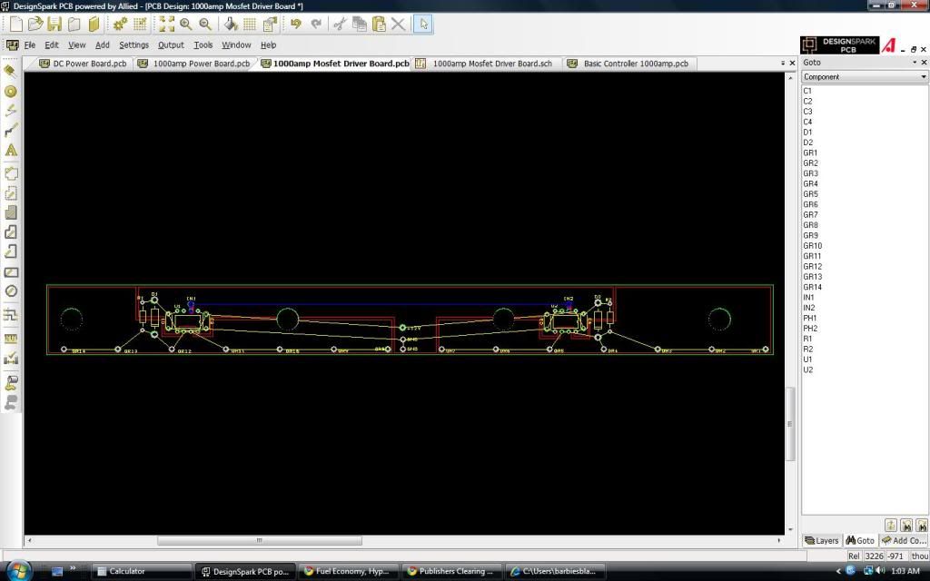
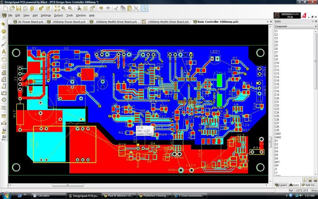
It doesn't matter as much to have the path from the optocoupler output to the driver inputs to be long. The 4 holes in the board are where the 4 mounting screws bolt it down. The board just sits right on top of the steel reenforcing thing, and the control board will be just above that. The 1000amp standard (non SR) control board, with the driver section removed, and converted to surface mount is done, and the power section is done too. I wish I had a million dollars. The driver board for example is only $0.25 each in quantities of like 5000. haha. But they would biodegrade by the time 5000 people got one.
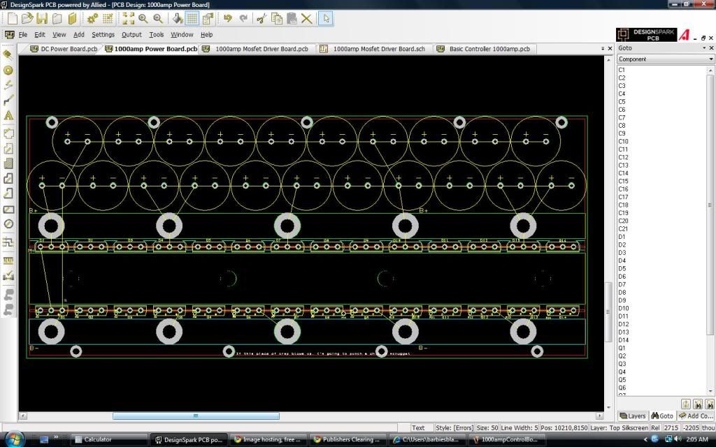
I was planning on trying 1/2" x 1/2" bus bars for B+ and B- and 1/4" x 1" bus bar for M- bar. Same cross sectional area, but does the cross sectional perimeter matter more if the electrons run on the surface? I don't know how it works. I was thinking I could drill and tap the end of a 1/2"x1/2" bus bar to give better contact. I was just considering 1/2"x1/2" because it can take a sizeable chunk out of the length of the path that needs to be as short as possible.