Quote:
Originally Posted by NeilBlanchard

I had fun doing it -- and I now know how I'm going to build my CarBEN EV prototype shell. The 1/4" polystyrene is a revelation for doing compound curves.
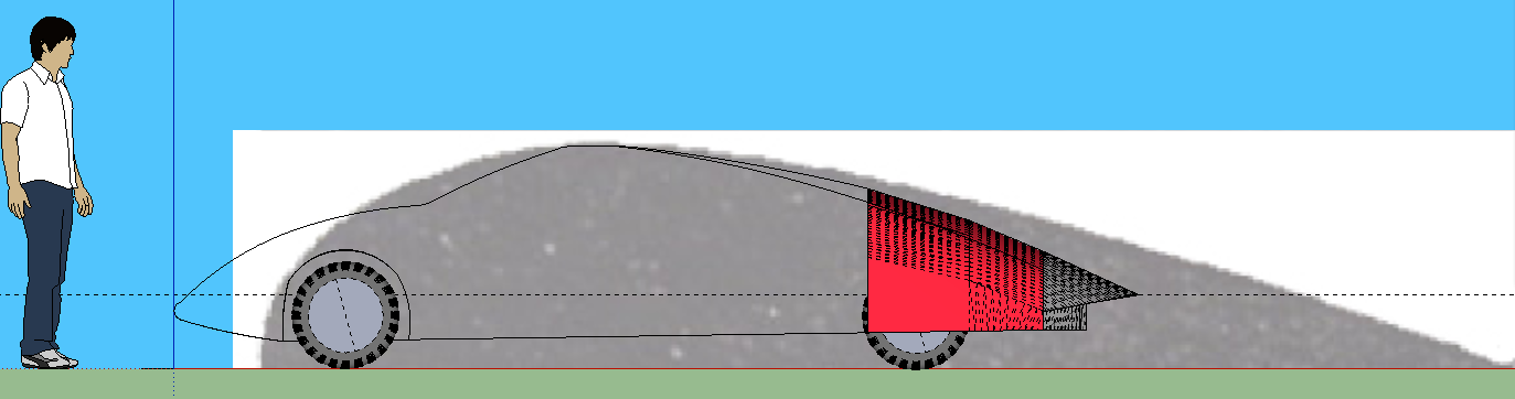
The 12 degree slope in the thesis was for a straight surface, and the slope was only on the top. The 3D cap shows how a curved surface can work better -- and there have been a lot of discussions here on EM with 15d slope being ideal, and even 18d works on cars like the EV1 because of the air flows in from the sides, as well.
I'll look around for the "ideal profile" image and see how it lines up with this cap? And it is no "recurve" like the prototype, so the main descending surface is much longer than previously.
[Edit: Here's the "ideal profile compared to the SU cap model:

So, the cap may be a little steeper than ideal -- I'll try a less steep version.]
The comment about the side mirror sight lines not being blocked by the cap is something I had not thought about.
[Edit 2: On the other hand, here's the EV1 compared to the ideal profile:

As you can see, it deviates as much or more than the cap. And here's the Dolphin:
I think the profile is a fine 2D guide, but is 3D, the air can flow in from the sides so the taper can be steeper *if* the sides are also tapered?
What do you folks think?] |
Neil,I've been looking over Hucho'sfastback and boat tailing work at Volkswagen.He published SAE paper 760185 along with Janssen and Emmelmann and this work is in his 1st English version book.
First off,the fastback lowered the 'squareback' drag from Cd 0.44 to Cd 0.34,and this was with straight sides,no plan taper.
--------------------------------------------------------------------------
In his Fig.23,pg 14 ( Paper )/ Fig.4.43,pg.142 ( book ) Hucho lays out different boat tail forms for a car like a Jetta with a graph of the associated Cds.
The length of car body concerned is about the last 1,010mm ( 40.4" ).
--------------------------------------------------------------------------
The body was pulled 'in' at the back in 50mm increments,up to a total of 200mm.
The tangent angles for each increment,measured at 'breakaway' ranged from 7-degrees, to 25-degrees.
-------------------------------------------------------------------------- The greatest drag reduction occurred with a contraction of 125mm@ a tangent angle of 16.5-degrees ( at the 40.4-inch span ).
Increasing the contraction beyond 16.5-degrees provided zero additional drag reduction.
-------------------------------------------------------------------------- On the 200mm contraction the tangent angle reaches beyond 22-degrees at a position equal to the beginning of the rear bumper.
In this same paper,Hucho describes 23-degrees tangent angle as the extreme limit.
W.A.Mair's boat tail research limited boat tail angles to a maximum of 22-degrees,and you couldn't get to that angle in anything less than about 1.3 vehicle heights distance down the body from where it was 'flat.'
-------------------------------------------------------------------------- My T-100 has a 100-inch bed.The maximum contraction at 100-inches is 11-inches at each side.Tuft testing shows clean flow all the way to the end.The 'curve' of the sides start of course at zero,and grow progressively steeper just as in the Template.
--------------------------------------------------------------------------
If we were to plot a curve which intersected the 40.4-inch point and 5-inch (125mm) contraction,and 100-inch @ 11-inches ( approx. 275mm )contraction,this curve would be a 'sure thing.'
Depending on bed length,any member could just go to any position down the bed rail and measure the contraction distance directly,all the way to the tailgate.There should be absolutely zero possibility for flow separation if a cap were built to this 'template.
-------------------------------------------------------------------------
And VARN mentioned the fillets and I totally agree.You'll notice that all high performance aircraft have wing root fillets to smooth pressure spikes at these locations.Also,Ford's Probe-V roof structure is so well blended into the body,that if you didn't have paint and glass to distinguish the greenhouse from the body,you'd never know where one began and the other left off.The air loves this sort of thing and I like this part very much about the Thesis.