Alright, Here is an update on the charger.
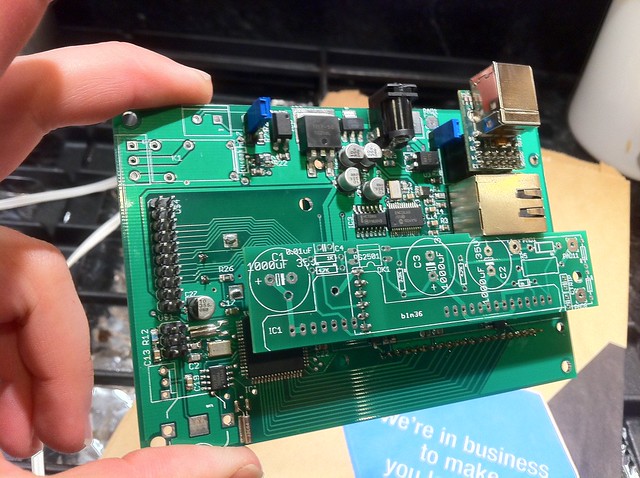
The boards that I ordered came in a few weeks ago. I had ordered the main control board, 2 different driver boards and a AC/DC digital isolated sense board. Heres a pic.
 Untitled
 by
AdamBrunette, on Flickr
The main control board has a graphic LCD panel that is 128x64 pixels. The user interface is super simple design. A rotary knob with push to select. You will just turn the knob to scroll to the option you want or increase or decrease values and then push the knob to select or set a value. Its very user friendly. The board is powered from a wide range of voltages. A switching power supply has been included to regulate from 9 to 24V down to 5V for logic. The input to the main board is traced over to the modular driver section. The driver requires an isolated dc-dc if isolation is required. The isolated dc-dc converter was not included on the main board because power requirements is dependent on the driver used. To have a universal dc-dc onboard would only increase costs. Also included on the main board is a 10-TBASE ethernet connection for remote monitoring and control of the charger. A real time clock (RTC) which will allow the charger to keep track of what day and time it is. This way you can set up charge schedules to limit the charging power or charge at all to times where power isnt so expensive or whatever reason you want. I also included the features I listed before. BMS input od 5V or 12V, Vehicle interlock relay featuring NO and NC terminals. Also a MOSFET circuit to control a contactor on the DC bus common to the dc supply to the main board.
The driver boards are modular in this design. I thought this could be good for people that want flexibility in power and price. You will be able to choose a high power driver, which uses the VLA-502-01 Powerex driver module. This is a 12A high frequency (30-70khz) driver module with built in dc-dc converter and Vsat detection. This is mainly for IGBT's.
The other driver board I designed and ordered is one just for prototyping. I will use this one to break out the signals for PWM, +5v, +VIN, GND, and an adc pin that can be used for feedback. I will use this board to design a driver based on what the cougar uses. It will be good for simple and smaller MOSFET based power sections.
The last board I ordered is the AC/DC sense board. My plan for this board was to use an energy metering IC for accurate measurement of current and voltage. Current is measured using a 0.001R shunt resistor while voltage is measured with a voltage divider and filter circuit. The board has an on board AVR to talk to the metering IC over SPI. It then converts this data and sends it over serial to the main board over an isolated connection. It is a very accurate method for measuring these sources, but it is not as fast as hall sensors. Due to the cost of this one and its speed, I will not be using this board as planed to monitor DC output from the charger. It will be an optional input for monitoring AC power only. The chip is more suited to this anyways. it can measure Power Factor, apparent power, reactive power active power and much much more.
Alright time for some pics.
 Untitled
 by
AdamBrunette, on Flickr
 Untitled
 by
AdamBrunette, on Flickr
Here is the back of the main board with the unpopulated vla-502-01 driver board.
 Untitled
 by
AdamBrunette, on Flickr
Here is a pic of the GLCD showing a map of the earth.
So I have tested all hardware functions of the main board. I have found a bunch of design charges that need to be made. Some are my mistakes in layout, others are things I would like to operate differently. Such as contrast adjustment. I will be changing to a different digital pot.
I am currently saving up to order the Alpha PCB's. Hopefully in the next few weeks I will have enough to order the boards and the new parts.
On the side of this project, I am working on a PFC power section. I wil post more on that when Ive made some progress.