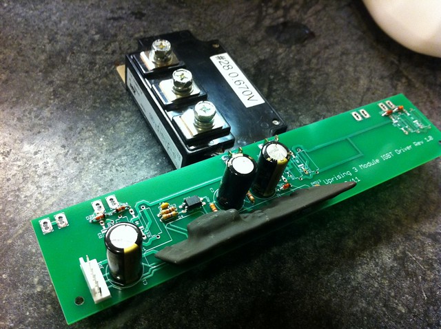
Well this weekend I was able to start testing the 3 module driver board. I assembled the driver section up to the gate resistors. I started adding gate resistors with just a 3R3 for on and off. This yielded slower then I had thought rise and fall times.
 Untitled
 by
AdamBrunette, on Flickr
 Untitled
 by
AdamBrunette, on Flickr
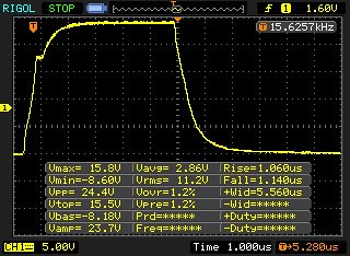
Heres a scope shot of the single 3R3 gate resistor. (Switching at 16kHz)
 3R3GateOnOff
 by
AdamBrunette, on Flickr
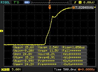
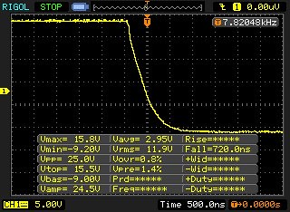
After this, I decided to speed up the turn off as much as I could without going overboard. The recommended gate resistor value is 3.1R so I went a little smaller with 3.0R. This is put in parallel with the 3.3R with a ultra fast diode blocking it from being used for turn on. This yield's about 1.57R for turn off. This dropped turn off times from 1.14uS to 720nS. This is still considerably slower then the 250nS fall time in the spec sheet. The spec sheet is talking about switch side and not gate side though. This could all change later today when I connect an actual battery and load motor.
Here is a scope shot of the rise. (Switching at 8kHz)
 3R3On 3ROff Rise
 by
AdamBrunette, on Flickr
Here is a scope shot of the fall. (Switching at 8kHz)
 3R3On 3ROff Fall
 by
AdamBrunette, on Flickr
On a side note, I have been doing some loss simulation calculations and have found out that in order to get the 1000A out of 3 modules, and keep them from overheating, The controller will have to run at 8khz.
Here are screen shots of 16khz and 8khz. Look at switching loss's for each and junction temp average.
 Screen shot 2011-12-11 at 11.14.14 PM
 by
AdamBrunette, on Flickr
 Screen shot 2011-12-11 at 11.14.01 PM
 by
AdamBrunette, on Flickr
-Adam