It's basically 99.999% done! I'm just debugging the control board a bit. One error was, I set the undervoltage trip point for the 15v supply to 15 volts. hahaha. Fortunately I had a resistor that was just right for setting the undervoltage trip point to 12.5 volts. The 15v output from the DC-DC converter drops to 12.5 volts when the 12v input drops to 6.7 volts. ya! So, if the battery powering the control board has a SERIOUS case of the sags, everything will still work fine, until it drops to 6.7v that is. Then the control board will gently shut everything down. Or if the 15v supply quits working it's also no biggie. And if the 5v supply quits it's also OK.
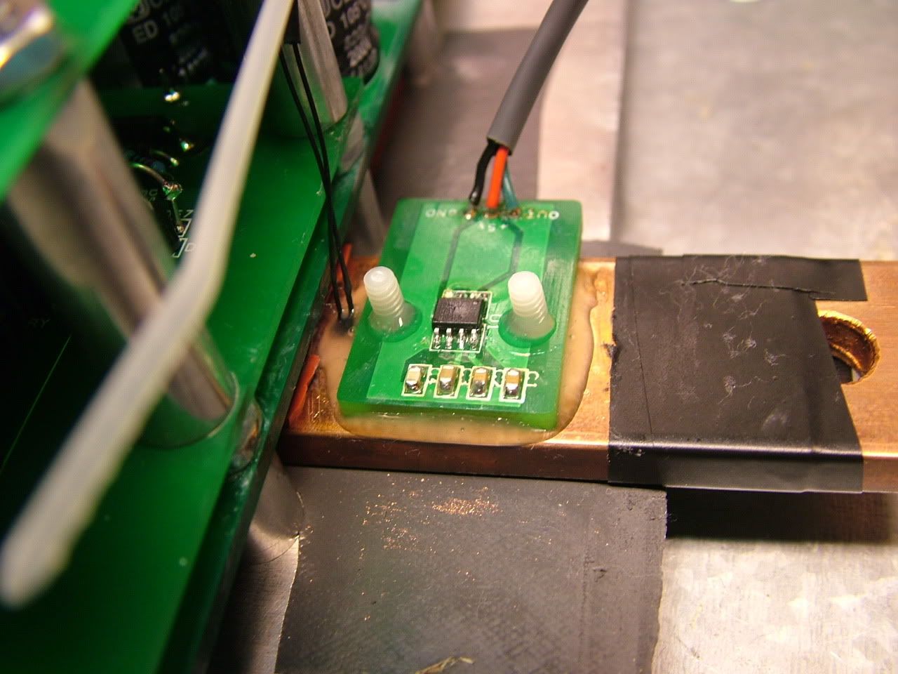
One minor catastrophe was I forgot to put the screws through the M- bar for mounting the current sensor. So then I slathered jb weld on the bar and squashed the sensor down onto it, and then I had a sudden flash of memory! That stuff is like 20% Iron Powder!!! That's not good! It's going to jack up my magnetic field. So I wiped it off before it dried. Man I love the smell of that stuff. I'm actually tempted to eat it. So then I got some 2 part clear epoxy that dries in 5 minutes and that sensor will never come off ever. Never ever. I centered it using the nylon screws with the heads cut off into the holes:

Heart attack averted!
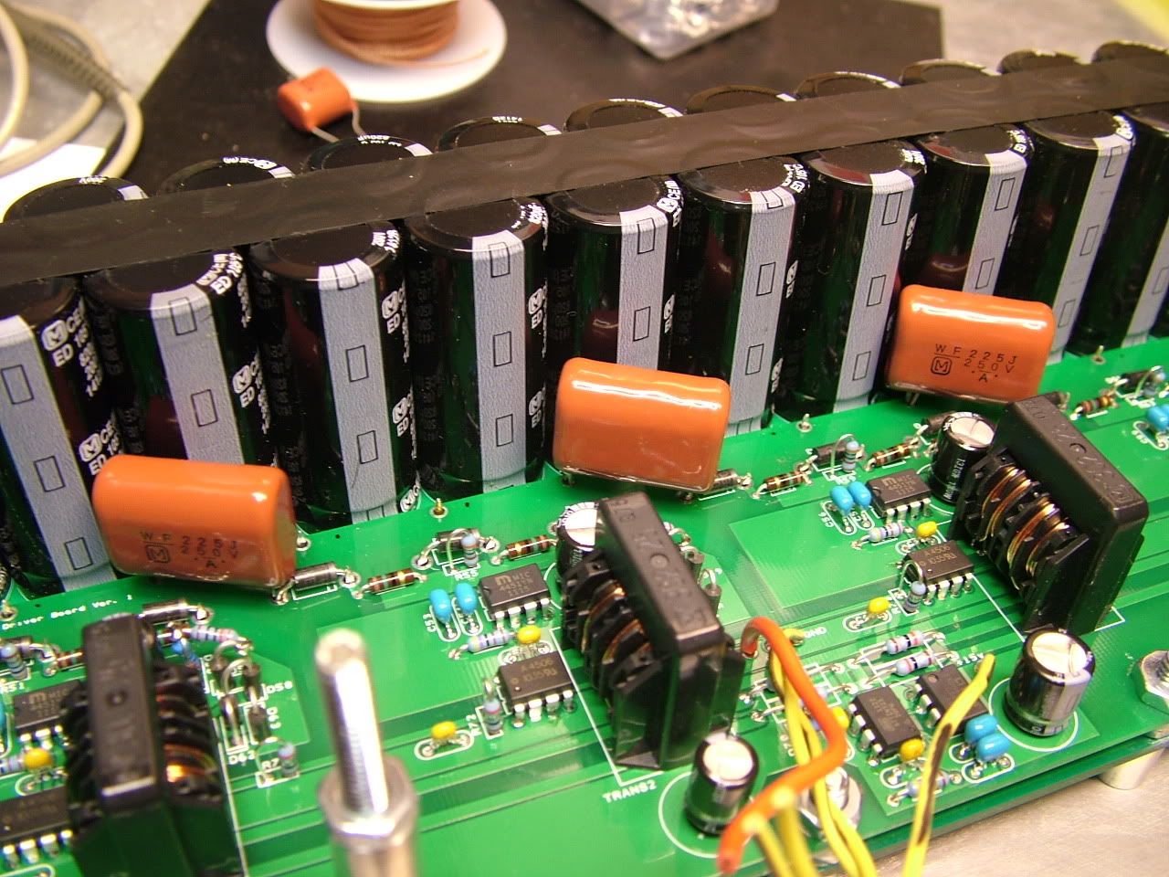
I also added a few polypropylene caps and the TVS diodes. I jb welded the poly caps to the electrolytic caps just a bit so they won't vibrate loose:

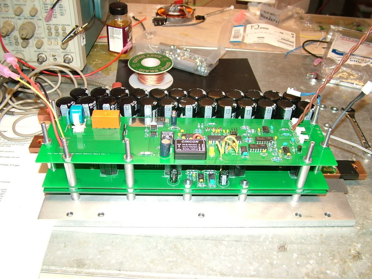
Here's a picture of it basically done. I still need to solder the pwm, +5v, ground and 15v wires to the control board. I just wanted to make sure the control board worked as I hoped, since there were quite a few changes:

It's about 3.25" tall from the top of the baseplate to the top of the precharge resistor. I forgot to add a spot for a diode for the relay coil, so I'll have to add that on the underside of the board for now.
I tested the PWM after the mosfet driver, so the board can put out a 5v PWM signal of basically any current that is needed. I need about 60 mA from mine.