Well I spent some time this weekend tuning the driver board. I ordered new carbon composition resistors and matched them in groups of 4 to make specific high tolerance values.
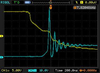
I first started with 3.0R because I messed up with my meter and didnt offset the lead resistance of 0.1R. Heres a shot of what That looked like on the scope.
 NewFile7
 by
AdamBrunette, on Flickr
You can see the turn off was ringing like crazy. It would actually turn the switch fully on with the ring.
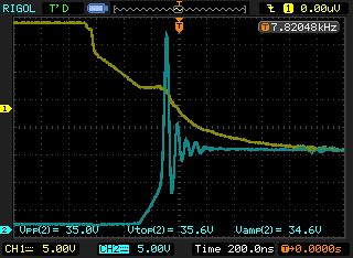
I then went to 3.65R and it started looking alot beter. But im curious why there is still such a large ring... I plan to try 4 parallel 16R resistors for about 4R gate resistance and see if that helps. I want to stay as small as possible because switching loss's are already high enough. I dont want to counter my slower 8khz frequency with long switching times.
 NewFile17
 by
AdamBrunette, on Flickr
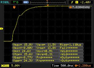
The turn on of the module has always been pretty good.
NewFile8 | Flickr - Photo Sharing!
Here are the shots of turn on and off with the 3.0 gate resistor. They look pretty good.
Turn on:
 NewFile1
 by
AdamBrunette, on Flickr
Turn Off:
 NewFile2
 by
AdamBrunette, on Flickr
Heres a longer time withe the gate off for comparasion
 NewFile20
 by
AdamBrunette, on Flickr
This is where I left it. About 33V spike on turn off. This is down from about 68V!!
 NewFile22
 by
AdamBrunette, on Flickr
Heres what damien was seeing on his controller. 5V/div 20uS/div
 ce1
ce1 by
AdamBrunette, on Flickr
More testing tonight!!
-Adam