ALRIGHT!
Last night I was able to finish tuning the driver board. I did have some good scope shots, but my computer crashed when I tried to open them and they got currupt....

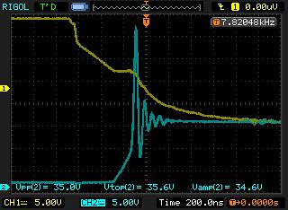
Yesterday I showed you this shot:
 NewFile17
 by
AdamBrunette, on Flickr
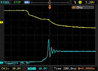
There is about 35V P-P. Well even though I lost my best capture, I have this one thats very close.
 NewFile23
 by
AdamBrunette, on Flickr
The scale is a little different, but you can see its getting better. The one I lost was showing about 22 or 24v P-P. I will get a new shot tonight. It also has very little ringing now. This is were I will leave it.
I ended up adding a diode to the turn on resistor and re-installed the turn off one. I am now running a 3.3R wire wound turn on, while not the ideal type, the inductance of the wire really helped without adding any other parts. The turn off is 2 carbon composition resistors 16R in value. In this pair, they create a resistor that is 8.45R. The carbon composition resistors tolerance sucks.... You cannot find 2 that are the same. While when I measure the 3.3R wire wound one, the 3 I picked are identical.
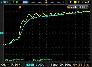
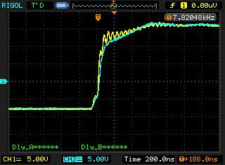
I was also able to measure some delays. From the driver to the gates everything is in the range of delay of 12nS max. And from one gate to the next, they are all in sync better then my scope can measure. Somewhere around < 3nS. Im pretty happy with this.
Here are the shots of rise from driver module to a gate.
 NewFile25
 by
AdamBrunette, on Flickr
 NewFile26
 by
AdamBrunette, on Flickr
And delays between modules.
Rise:
 NewFile27
 by
AdamBrunette, on Flickr
Fall:
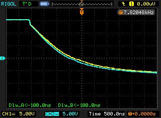 NewFile28
 by
AdamBrunette, on Flickr
I will be doing high power and voltage tests starting tonight.
-Adam