Recently obtained some "3 Watt" rated cheapo white leds from ebay and decided to experiment with them for automotive use.
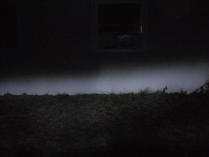
Easy to make DRL lamps or some high beam augmentation lights but I wanted to see how hard it is to create the cutoff and the little step up in the beam to the right of the center point of the projected beam.
The opportunity came up after I put window tint on our house and I had all this mirrored tint film left over. ( that is the mirror for the LEDs ).
Three LEDs connected in series and resistor values dialed in so the group of three LEDs draw around 200mA at 12.4 (ish) volts.
(That is less than half of rated power for now. Maybe later I will crank them up a little.)
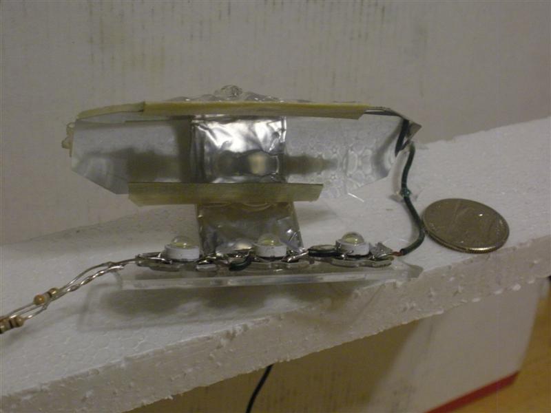
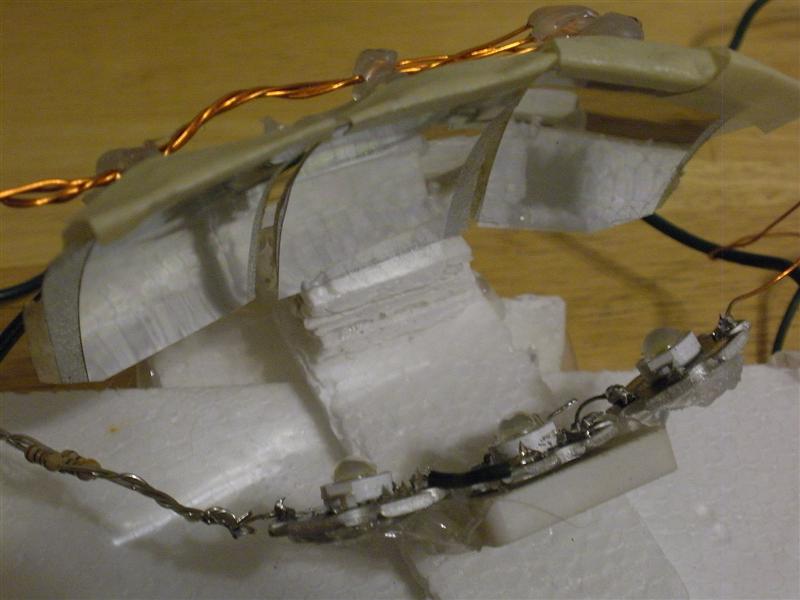
I use two of these mirror assemblies each with 3 LEDs infront of the mirrors.
(total of 6 LEDs with a 400mA draw from a resting 12V lead acid battery after the two groups are parallell connected.)
For now very ugly as I just hot glued them to a piece of styrofoam,but this is not a beauty contest.
However it is still ugly enough that I'm just going to show a beam shot to the side of the house first.
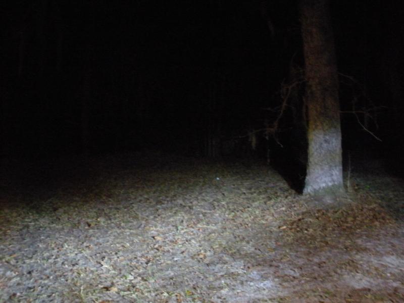
Another shot on the yard including a tree in the beam of light.
This is about 7W of power as I switched to a lithium pack with 13.3V to power it for these pictures.
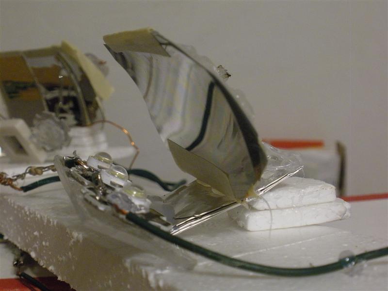
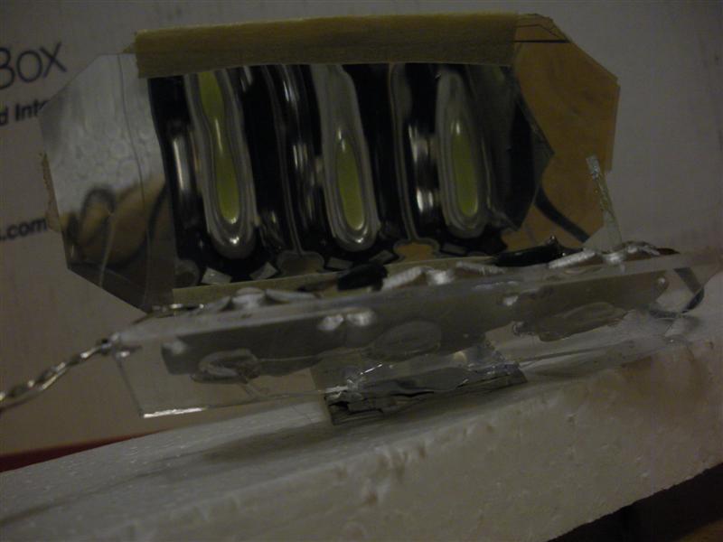
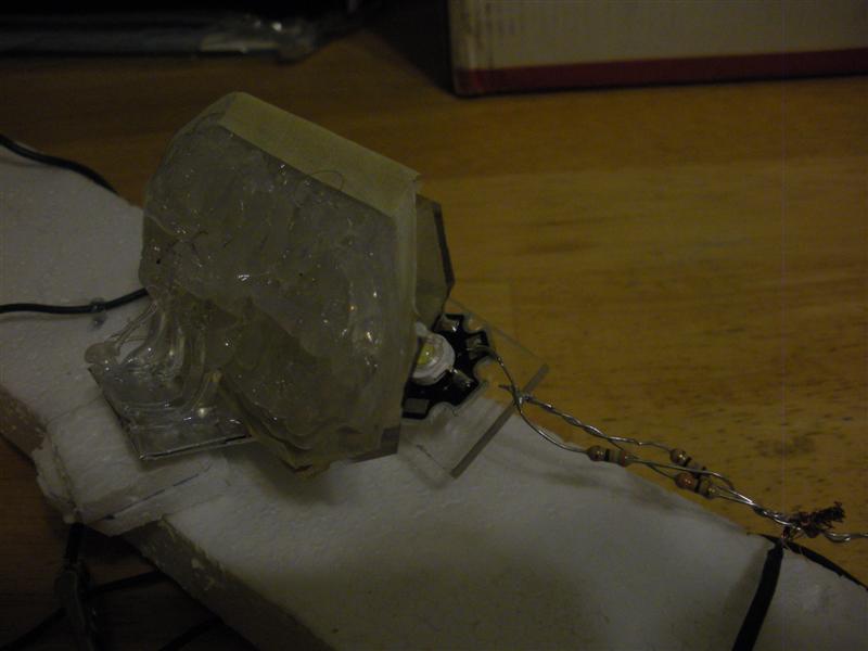
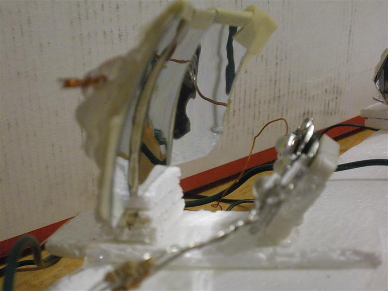
Here is the test rig. The one on the right side is a single piece of curved mirrored foil formed over a round object like the side of a small bucket.
Taped down with masking tape,then a thick layer of hot glue on the back side helps it hold the curved shape after it is cut off of the side of the little bucket with a razor knife.
The beam is very wide so for the next mirror (left side) I tried three pieces of curved mirrors aiming inward as an attempt to narrow the beam and try to concentrate it better.
Also both mirror assemblies aiming inward in relation to eachother and the beam is still very wide.

Some closeup shots of the one piece mirror:
Back side:
The three piece mirror:
Viewing it head on above the cutoff line:

Below the cutoff line. (in the beam):

BTW the LEDs are facing backwards and up at the mirrors and the mirrors are projecting the beam forward.So there is no direct glare (minus imperfections) looking at it head on above the cutoff line!
The pieces of masking tape near the edges of the mirror are there to clean up the beam from stray reflections due to tiny wrinkles/damage from me cutting it off of the curvature forming bucket!
Also the hot glue has to be applied very slowly in small quantities,allowing time to cool off quickly,not letting the heat get to the mirrored foil or it is going to wrinkle the foil ever so slightly even through a layer of tape and it will project an extremely spotty image!
Barna