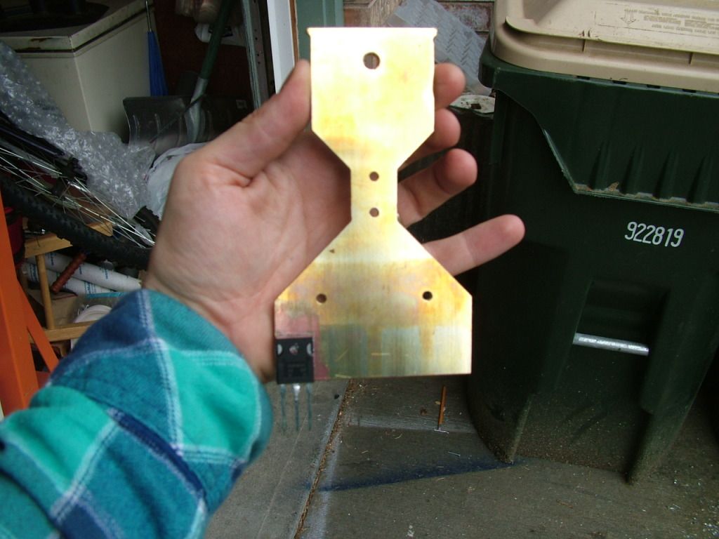
I practiced different solder techniques yesterday for the TO-247 package backs to bus bars. I put a sample of paste on the Middle leg (it's connected to the back), and then put the component on a bar that is around 450-500 degF. It takes 5 seconds for the middle leg to melt the solder, and then I give it 5 seconds in melted state and then put it in a water bath. It cools in just a couple seconds. Here's some soldering of one of the phases of the AC controller (by the way, the skinny area in the middle is where the current sensor goes. Skinnier makes the current sensor more sensitive.:

That's going to actually be 4 igbts per phase later, but just one free (Thanks Rod Hower!!!) 50amp igbt per phase for testing.
I also ordered a 48 pound 200amp inductor that I'm going to use with testing the controller. I know I know, some resistance also needs to be added to increase the PWM duty and not just test the freewheel diode! haha. I have that covered too. This move proved necessary since my crappy motor threw some bars that the brushes rub against when it ran full tilt at around 120v. It was also rated for 24v. Man, that was friggen scary. Long story, must go to school!