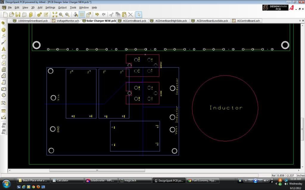
I've got like 10 control boards and driver boards for the 1000amp high side controller. One of the advantages of the high side configuration is that you can use it as a buck charger. A different power section is necessary though because of the higher voltage used in charging. Here's a layout. Basically I'm just using one of the 6 isolated supplies from the driver board to turn on/off the single mosfet I'm using. It's so simple when powered from a solar array. Just do 100% duty on the mosfet until the voltage comes up to around 13.8v per battery, then hold the voltage constant until the current falls to "x", then drop the duty down until the voltage per battery is around 13.6 or 13.7. Easy peasy japanesy! With a single diode/mosfet ($20 for diode, $38 for mosfet), you can charge at a rate of around 9 or 10kW. You don't have to have much in the way of input filter capacitor, because it's DC input!
I just ordered the rest of the parts for the charger/inverter. The inverter has has outputs of 110v, 110v & 220v. But what I'll probably do is just use the 220v, fed into a 220v voltage stabilizer, and then plug that into a 4 wire 50amp generator plug.