Quote:
Originally Posted by 95curd

nice bulid! looks like it's coming together real nice. Are you planning on any luxuries like radio and AC?
|
The car never had AC. But it does have a fully functional 6-CD changer in the trunk (a la 1992).
-Top Speed on flat ground (so far): 80 km/h and still accelerating. I just haven't had the opportunity nor the space to do a true top speed run yet.
-Range: I have no idea. But it gets me to work and gets me back from work without putting a dent in the system voltmeter's reading.
-Charging time: after 6.5 km (with a big downhill) commute to work, three hours; after the commute home (with a big uphill), four hours.
A question that I have been asked three times in the last two days is:
"Have you thought about putting an alternator on the drive axle so you can charge the batteries while you drive?"
Oi. As a response, I usually refer to this video:
http://www.lghs.net/ourpages/users/d...boardMotor.mov
Field Power Problems
Yesterday I installed a larger relay to turn the field on and off - a relay that closely resembles a starter relay on some Ford vehicles. Now that the field power is being interupted with the larger relay, there is no arcing or funny relay noises even with 48 volts going to it. I seem to have solved this arcing issue for the time being. I am not sure the field voltage choice relay will last very long with the amount current I am forcing through it (it is merely a plastic, square 40A 5-pin relay) but I guess I will have to find out the hard way. I do have a spare relay in the glove box after all!
The other day I measured field current, which for power curve sakes is probably a more important figure than field voltage. But it turns out that the field winding resistance is exactly one ohm, so 12.5V applied = 12.5 amps, 25V = 25 amps, etc. Now I am at 48V for start off, and it makes quite a difference in torque. Most times I can take off from a stop in second gear.
Battery Diagnostics
I was originally going to install six small digital volt meters in an array to monitor each battery pair. I even bought a bunch of meters off eBay. However, in my great haste to get this car on the road I left them out. But it turns out that detecting bad batteries will not require individual volt meters.
Yesterday I charged the batteries after my commute home from work. I noticed that it took one pair an extra hour to charge, and one of these two batteries was making bubbling sounds. The next day when I got to work I immediately unhooked these two batteries from each other and measured their resting voltage. The one that had been bubbling while charging was a full volt lower than the other, so I charged it, removed it and load tested it. Yup, toast. 350 amps instantly brought it down to 7 volts. A battery should be about to handle half its cold cranking amps (these are 700CCA batteries) for 15 seconds and still be at 9.6V or greater. I quickly found a replacement in the core shed at work, tested it (9.8V on a load test) and replaced the dud. One the next full charge all of the chargers turned off within 15 minutes of each other. Problem solved. I guess this is another advantage of using individual 12 volt battery chargers.
Alltrax Controller
A buddy of mine lent me his remote inductive ammeter so I could monitor motor current. I am proud to say that Alltrax does not lie in their specs of 450A for two minutes and 350A for five minutes. On the way home from work yesterday I floored it all the way up the long hill. When I reached peak voltage (which is also peak power) and the current started to fall (57 km/h in second gear) I shifted into third and it held 450A all the way up the hill while still gaining speed. I am highly impressed with this controller.
Other than a little bit more tweaking and tinkering, I believe I can truly say that this project is quickly coming to a close. Today I finished my control panel that looks much better than the gaping hole under the radio:
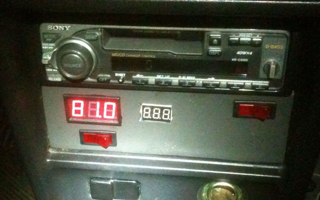
I absolutely love the old school red LED numbers. Dr. Emmett Brown would indeed be proud!
The extra meter in the centre will be the voltmeter for the 12V accessory battery. The switch on the right is the heater switch and the switch under the system voltmeter will be used to turn the voltmeter on and off. This switch is my solution to the fact that the [super cheap eBay] system voltmeter is causing a shared ground between the chassis and the traction system. I plan to power this voltmeter with a 9 volt battery through this switch to eliminate this problem.
Heater
I did use it today. It was pouring rain outside and about 10C. It was merely a ploy to keep the windshield from fogging up and it completely worked. When I got home I put the inductive ammeter on the supply wire: 7 amps. 72V X 7A = 504 watts. Not substantial, but it's better than nothing!
Here is a picture of the organized mess formerly known as the engine compartment:

I hope to have some videos soon. Until then, you will have to be patient!