Lately I have been working on a PWM field current controller idea. I really want to control my sepex motor properly to get full advantage of the whole sepex thing because my tiny motor needs all the help it can get! A proper Curtis 1244 (72V, 500A) controller is $1200 + the $200 PC programming kit + shipping + tax, and that's too much.
The field current relation to armature current needs to look like this:
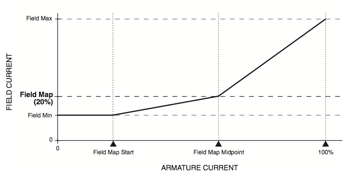
This means I need to measure armature current and turn my measurement into a 0-5V signal to give to a small PWM controller. I am thinking of using a 500A 75mV shunt and amplifying the 0-75mV signal to 0-5V.
Here is the schematic I have come up with:
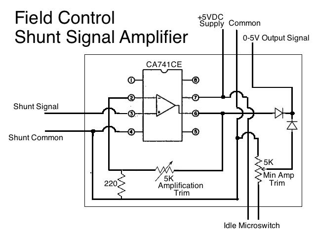
The CA741 is an OP-AMP chip.
The circuit has two parts:
1. Minimum field current. Switched on with idle microswitch. It ensures a min of ~10A field any time the throttle is depressed. Adjustable with "Min Amp Trim".
2. Variable gain amplifier. Takes the 0-75mA created by the armature current shunt and converts it to a 0-5V output signal for the PWM field controller. Adjustable with "Amplification Trim". This 5K pot is Rb. The 220u resistor is Ra. The amplification formula is (Vout-Vin)/Vin = Rb/Ra.
I am not sure the two diodes are correct. The way I see it is the circuit with the highest voltage "wins" and that voltage is the output signal.
Any electronics gurus want to proof read my schematic and tell me if it will work?
EDIT: I see major flaws in this circuit. I have instead decided to use a 0-5VDC output amp transducer to measure current. More circuit diagrams to follow!