Quote:
Originally Posted by lunarhighway

Xringer
my car looks similar, and i've also wondered how to improve the area, but i'm also leaning towards the defuser theory. Maybe not even a defuser but rather a simple crude duct that leads the air that enters the wheelwell out under the car. however viewn from below it does looks pretty bad.
if i an correct in my assumption air passes trough the duct than building a clean duct in there that can deal with the same volume of air would be an improvement, you could fair over the big hole in the bottom and just leave an opening for the air to exit
aerohead
.Without a central spine,the panels would only work at zero-yaw angles,as in any crosswind condition, there would be no inter-connecting structure to contain the flow and prevent bleed-out.
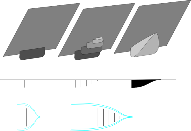
wouldn't this actually be a benefit? as the fairings intention is to direct air that goes front to back around a projection, however when the airflow comes in at an angle the original ideal solid fairing will sudenly become an obstruction to the air and ads frontal (or rather side) area to the profile, however with separate dams depending on the angle there will be less to no aditional frontal area and airflow will pass trough the fairing.
Their leading edges would require enough radius so as to allow flow separation,and each trailing panel would also require proper radius
could you please explain what you mean be "enough radius"? i was thinking of a series flat dams like this
 |
The flat panels as depicted would have a drag coefficient of Cd 1.11 individually,although training behind one another,the second unit on back would be somewhat shielded in the wake of the very first panel.With Cd 1.11,the flow would immediately separate at the edges of the first panel,and it is doubtful that it would re-attach anywhere.That being the case,even though each successive panel is a bit larger,they would probably be embedded within the wake of the first panel.I apologize that I do not have the proper references with me,however,I believe that a radius that is 3-percent of the width of the panel is sufficient to prevent separation.Some side-view mirrors will have this minimum curvature at their edges.They don't look aerodynamically efficient,however,exhaustive research done for the VW Vanagon established the bare-minimums for leading-edge attached flow and I believe it to be good science.If the minimum criteria are met,then I believe the air will flow over the segmented fairing at zero-yaw,however,as the air begins to attack from the side,I believe it will travel transversely,colliding with the leeward free-stream,causing a turbulence more amplified than with a unitary fairing structure.I don't know.It's just how I perceive it.Any circulation of the air is vortex-drag which must be invested with engine power.The central spine might capture and arrest the transverse flow,pooling within the panel elements,allowing the free-stream to flow over it as though it were more a solid,fully skinned fairing.The Continuum Dynamic's 18-wheeler boat-tail functions on this principle,and will not allow the air to venture beyond where an ideal teardrop's trailing edge would let it go.Another thought is that with enough panels,the mass of the material used,begins to approach and possibly exceed the mass of a fully-contained fairing.Just a thought.