I was planning on buying the 3 IGBT boards and just cutting them down. Will you build the 2 IGBT board if you get enough requests?
Thanks,
Darin
Quote:
Originally Posted by adamj12b

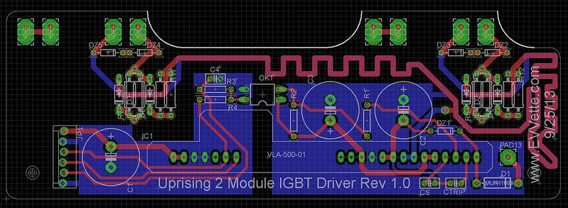 2 Module IGBT Driver
 by AdamBrunette, on Flickr
Here you go! 2 module version!
Email me for the eagle files if you want them.
As for the pads for the terminals, I just place 3 holes intersecting. It has not been a problem yet.
Diodes are MUR1100E.
The precharge circuit is as follows.
Pin 3 of the 23 pin connector is a connection to the B+ before contactors. This is feed through a 100R high power resistor, switched by Q8, an N channel MOSFET and then connects to the cap + terminal. The contactor output is justa 12V signal common to the 12V in the vehicle. The 15V dc-dc output shares a ground with the negative side of the capacitor. I dont think I realized this before. It was something I think I thought about thought about but did not correct because the Uprising driver has a second dc-dc and isolated the controls from the battery. I might need to look back into this. I dont want to add another dc-dc converter so the fet that switch's the precharge resistor. I didnt want to use the battery feed to power the fet as this would restrict what voltages could be used with the logic board. I want to be able to precharge anything between 12 and 400VDC.
-Adam |