There is still discussion about proper 'angles' for roof down-slope,for achieving the optimum drag reduction.
I expanded upon a drag table Hucho published in his 2nd-Edition book,based upon Rolf Buchheim and his associates research findings published in 1981.
As you can see,the best angle depends upon the length of the vehicle's aft-body,as a percentage of the vehicle's total length.
In the 5-illustrations,each image denotes the the angle which produces the lowest drag for its particular aft-body percentage.The original test model,with no roof angle is taken at an estimated Cd 0.50.
If the angle is either steeper,or more shallow,the drag will increase.
NOTE: These values are only for a vehicle with absolutely zero roof camber.Just a perfectly flat roof,as with JEEP Wrangler,HUMMER H-1,etc..
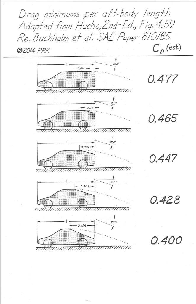
Here are the values I came up with for Xist's comparison:

Since some of the members are considering angled tails,I'll throw in a couple tables from the boat-tailer trailer thread:
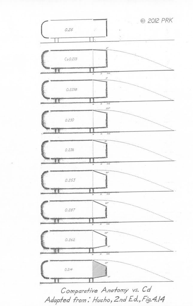
Here's one which factors in edge radii as well:
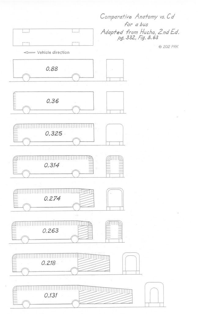
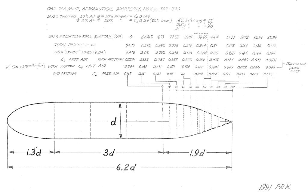
Here id W.A.Mair's boat-tail architecture recommendation:
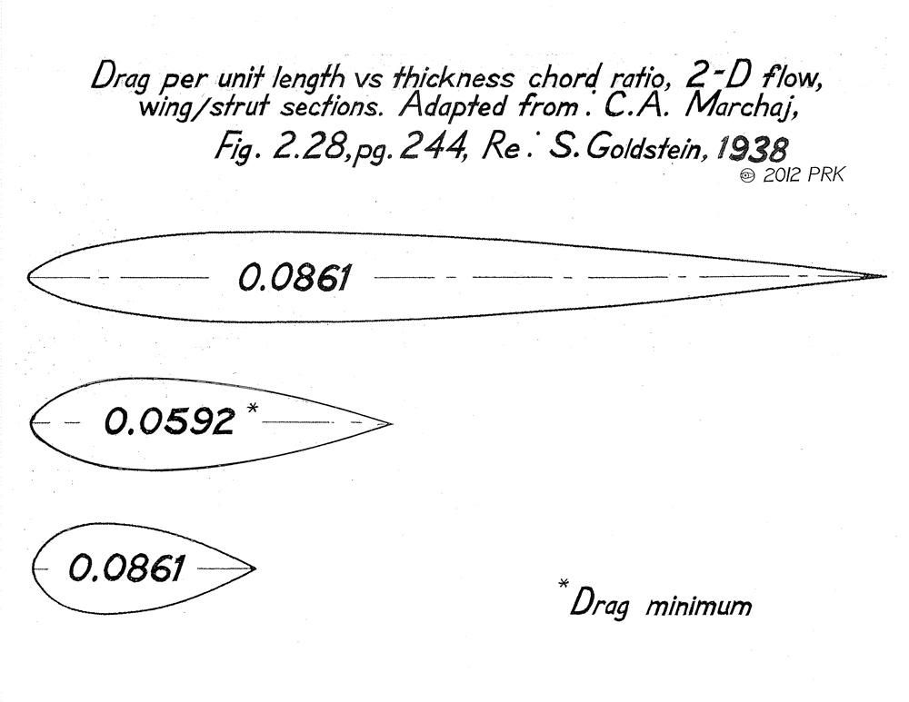
Here are some wing section drag comparisons which emphasize the importance of the aft-body :
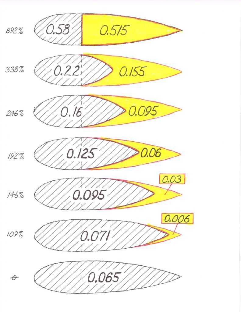
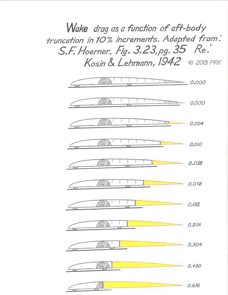
Here is a drag table illustrating the actual drag coefficient for the wake of a half-body -based vehicle,at varying degrees of aft-body truncation:
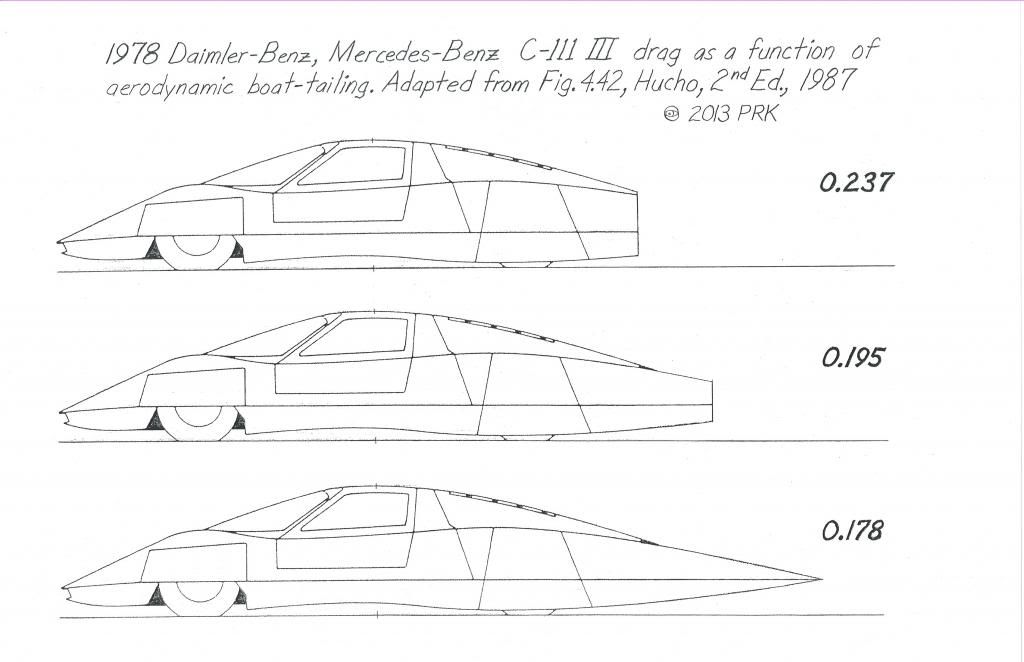
You can see the truncation effect illustrated here with the Daimler-Benz,Mercedes-Benz,1978 C-111 III record speed/fuel economy experimental car:
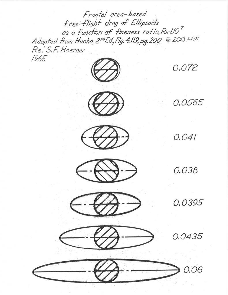
This table illustrates the "sweet-spot" for elliptical bodies of revolution,who's Cds are shared by streamline bodies of revolution of the same fineness ratio.Your car,and it's mirror-image below the ground define it's "effective" fineness ratio.:
This table illustrates the "sweet-spot" for streamline bodies of revolution which Hucho recommends we use,along with wing-derived bodies for the absolute lowest drag.You'll notice that the longest,and the shortest share the highest drag,and the Cd 0.029 represents the drag minimum.This specific form is essentially the Aerodynamic Streamlining Template.It has the lowest drag while still respecting the 22-degree aft-body slope needed to prevent separation.:

Here is a drag table for symmetrical wing sections of 2-D flow illustrating the "sweet-spot" for low drag.This center image has the lowest drag,and it's aft-body fineness ratio contour has shown up on many of the lowest drag vehicles ever measured.And it is what I recommend for use in plan-taper of any boat-tailing:
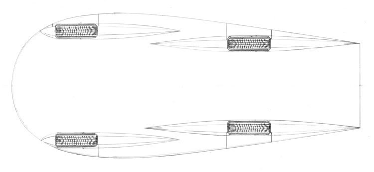
Here is a schematic of the underside of the Aerodynamic Streamlining Template,roughly utilizing the contour of the minimum drag symmetrical wing section.
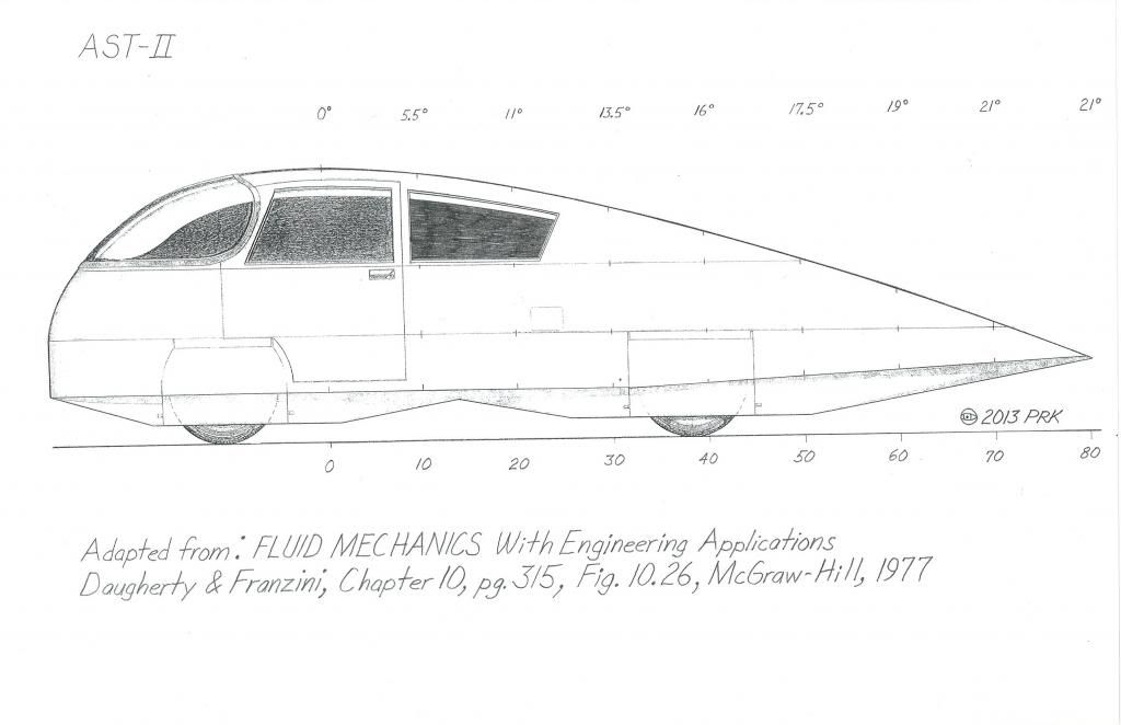
Here is a side elevation of the AST-II to help understand the belly image above:
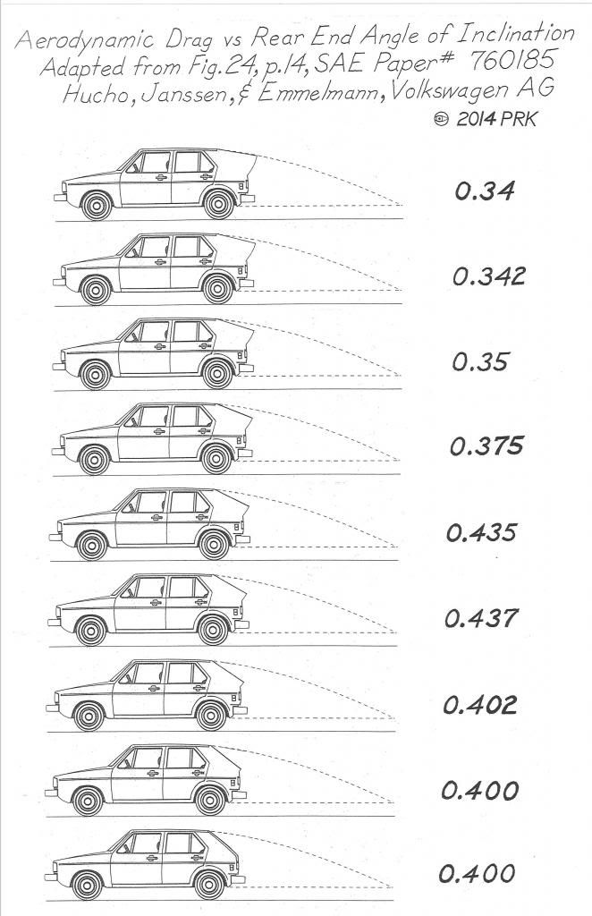
Here is table #14,which is derived from Hucho and associates,with their wind tunnel work on the Golf/Rabbit,Scirocco,and Polo,published in their SAE Paper # 760185,from 1976.
I could not find a true-length image of the Polo for which Hucho's original table showed in a vignette,so I've shown a Golf-1 which would have behaved similarly.
As you'll see,with optimized nose,edge radii,roof camber,vertical and body side camber,and tumblehome,the drag reaction to the rear slope angle behaves quite differently from the rudimentary and primitive models investigated by Bucheim et al.
NOTE: In this SAE Paper,Hucho mentions that beyond 23-degrees,the wake transitions to a squareback wake,and there is a critical range of angles at which the wake will alternately jump back and forth between a fastback wake and squareback,leading to exceptionally high drag.At about 38-degrees,the squareback wake is firmly established,and any further steepening of the slope has no affect at all on the drag.
W.A.Mair determined that 22-degrees is the critical angle not to exceed.Which is in close agreement with Hucho.
Here is a link to a current image from Mercedes-Benz.The bottom green line behind the roof depicts a 'surface' the air might like to see:
http://asset4.www5.mercedes-benz.com...im_Quadrat.jpg
Here is another image from the same site,illustrating what boat-tailing the aft-body will eliminate:
https://www.google.com/search?q=aero...F%3B1230%3B454
Here is an image of a very simple wind tunnel model :
http://i1.ytimg.com/vi/nrqwltq83FQ/hqdefault.jpg
Here is a NASA image of notchback drag
http://www.nasa.gov/images/content/4...5-012_full.jpg