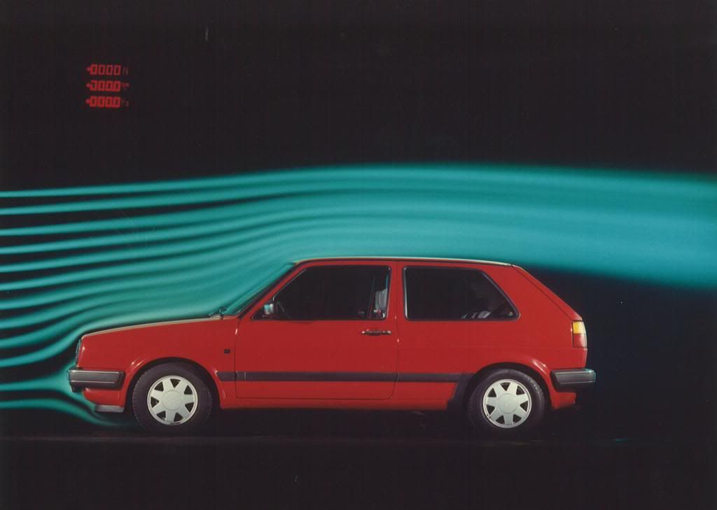
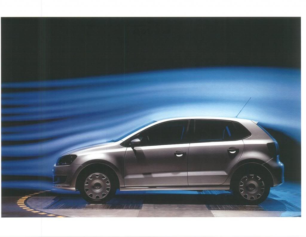
*With sharp leading edges separation is immediate,leading to high drag.
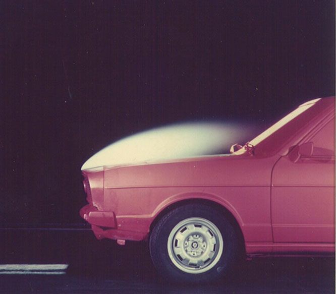
*With an 'optimum' nose,separation is eliminated and kinetic energy is conserved for downstream conversion to pressure rise
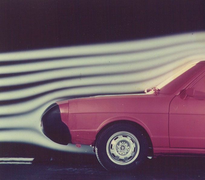
*With subtle softening of the leading edges,the same flow attachment is achieved as with the 'optimum' nose.
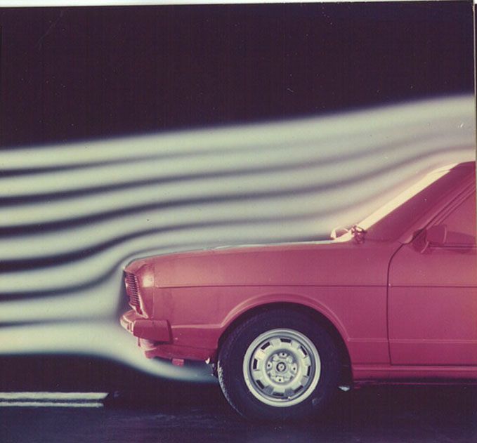
*With minimum softening,flow attachment is achieved as long as the roof,sides,and underfloor respect certain contours.
--------------------------------------------------------------------------
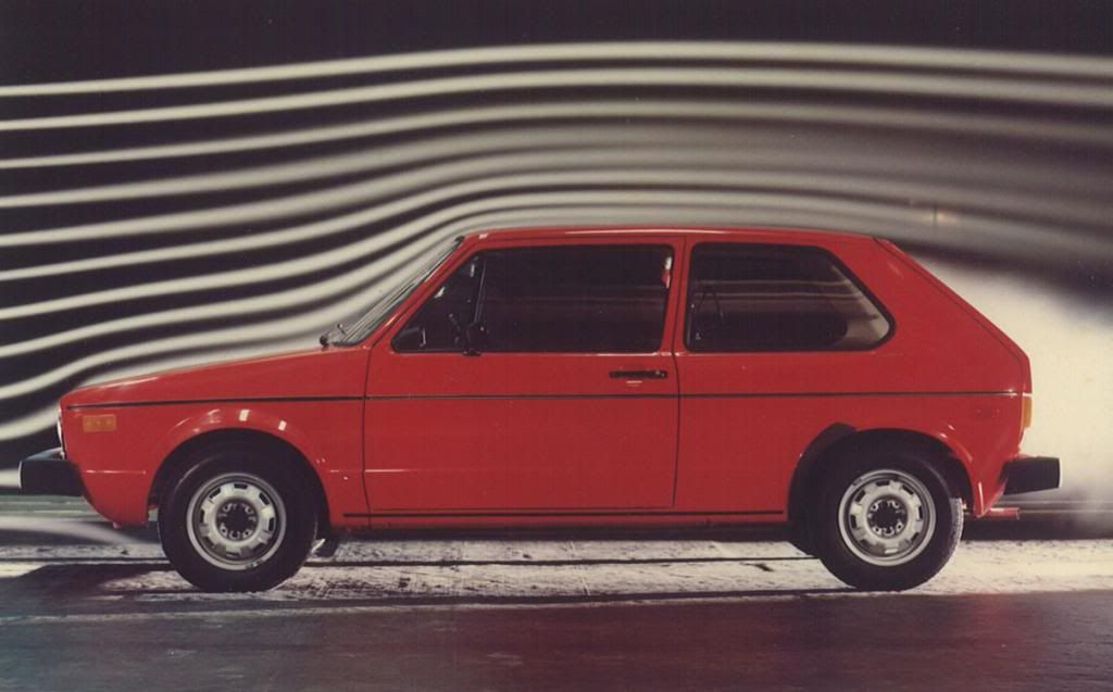
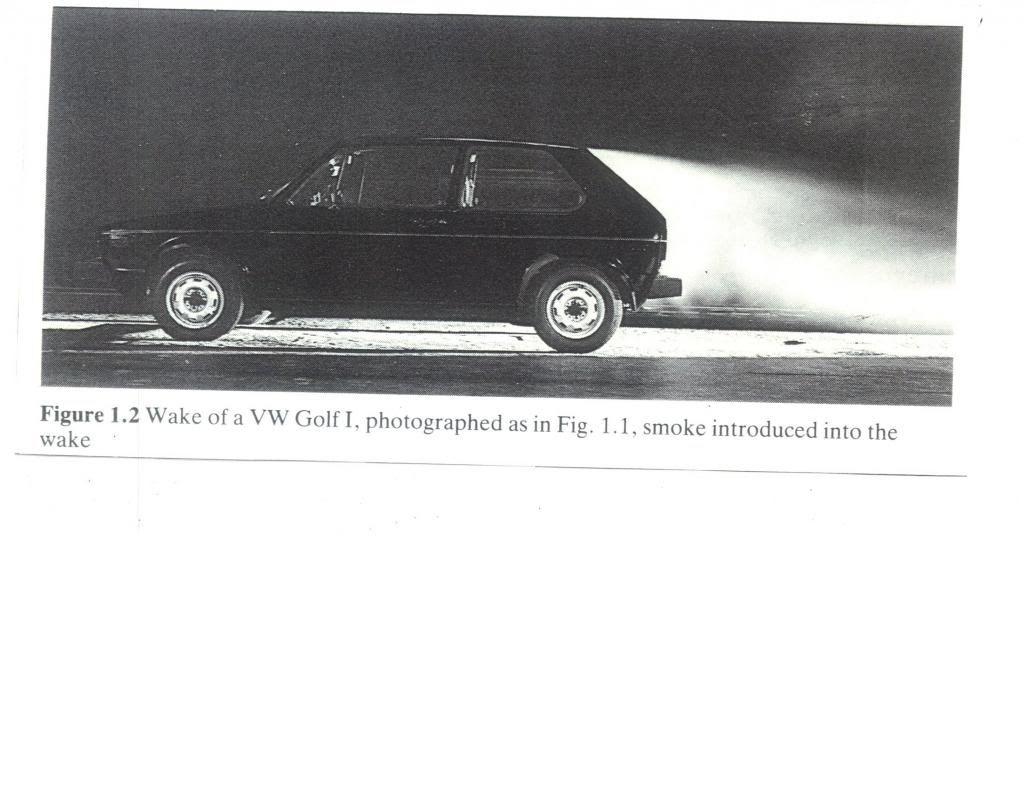
*The challenge for streamlining,is to reduce,or eliminate the low base pressure turbulent wake,who's eddies and turbulence cannot be converted to a pressure increase.
--------------------------------------------------------------------------
*Observation of the wake region itself suggests a flow contour which would support attached flow.
--------------------------------------------------------------------------
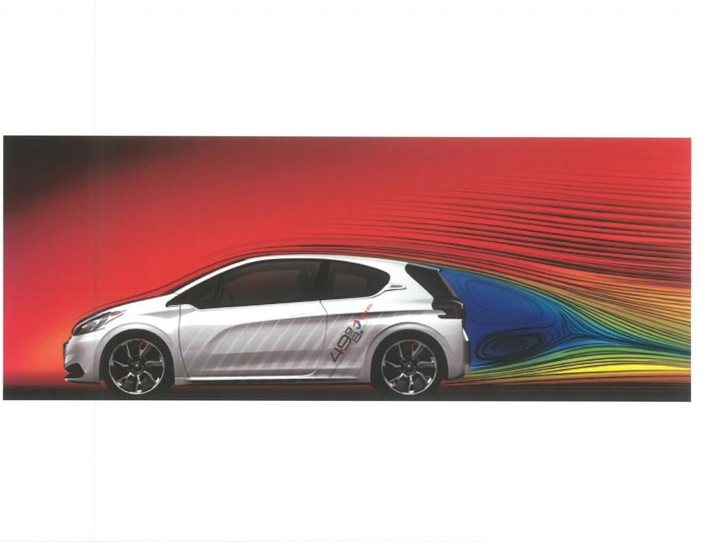
*With 'boat-tailing' we achieve the elongation necessary to reduce,or eliminate the separated wake.
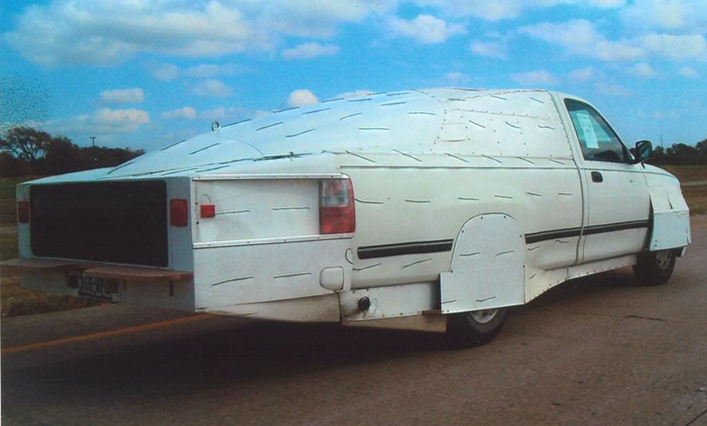
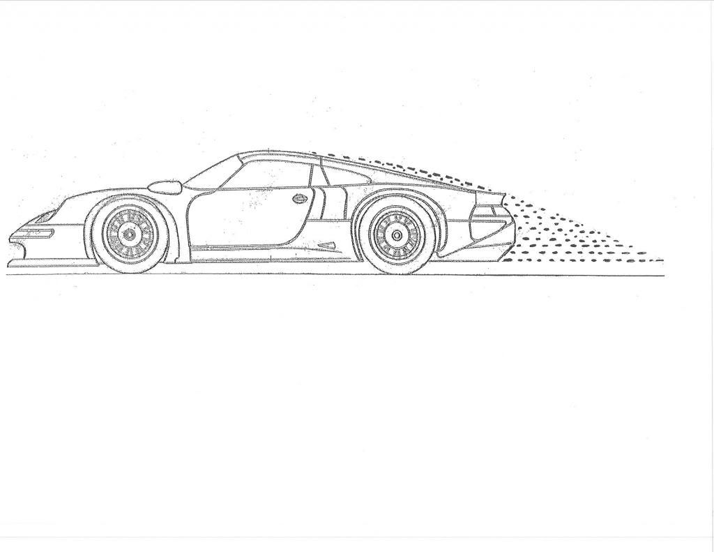
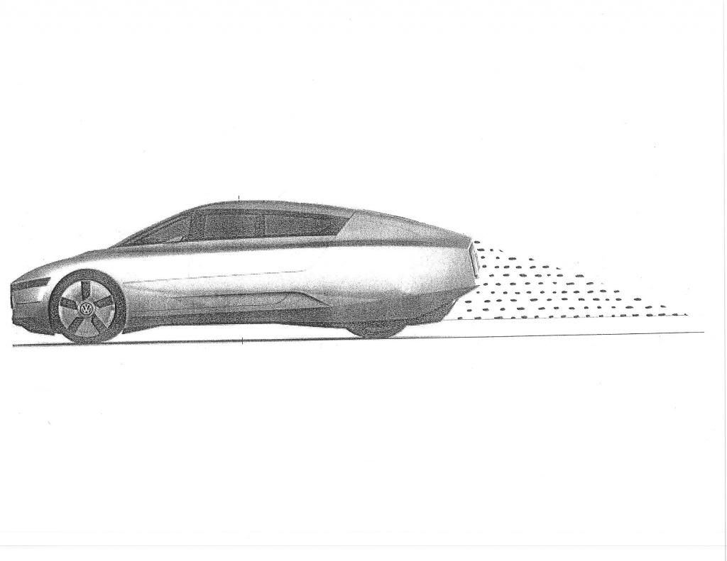
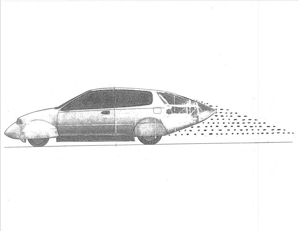


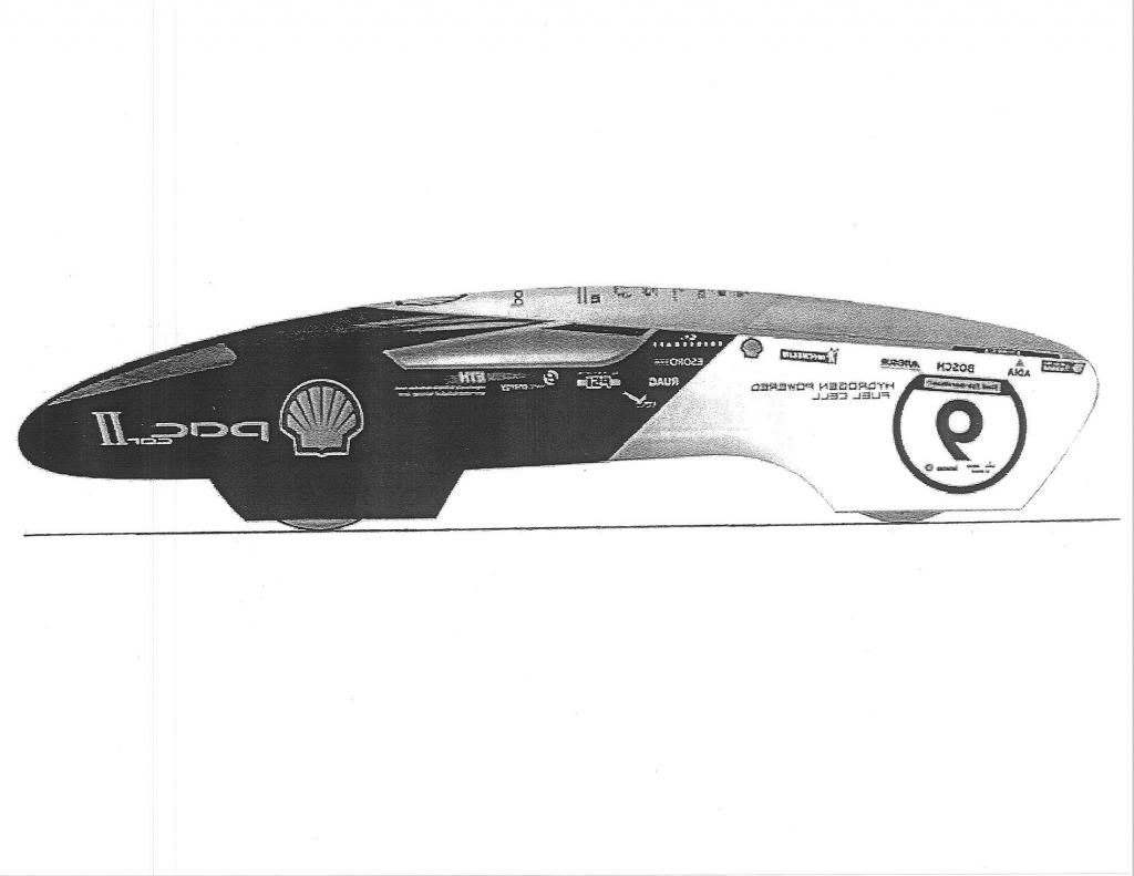
*This is a 2D flow image,however you can see how the flow comes apart when the aft-body contour is too 'fast.'
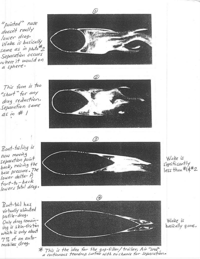
*The action is at the rear.This is prime real estate for drag reduction.
*Any automobile manufactured after the mid-1980s is a good candidate for the elongation and aft-body mods necessary for significant drag reduction.

*Here is the 'golf ball' effect of the turbulent boundary layer's ability to 'hold' the air against the aft-body,even though it would like to flow backwards,upstream,towards the low pressure region preceding the position of max camber as shown with the laminar boundary layer.The contour,between the 12:00 o'clock position and 4-seconds after,or 6:00 o'clock and 4-seconds before,is essentially the aerodynamic streamlining template.
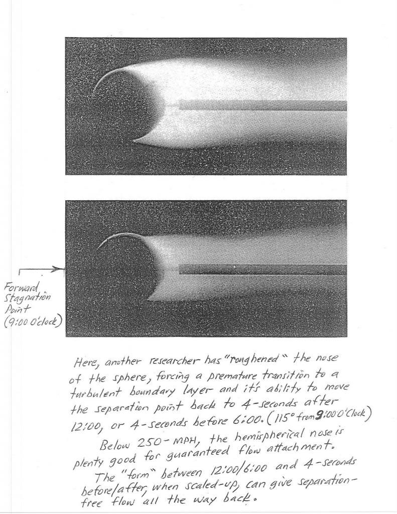
Here is the same thing happening underwater with a bowling ball.US NAVY researchers have glued sand to the forward stagnation area to induce an immediate transition to TBL,and as you can see,the separation point is moved back 4-seconds of clock sweep.
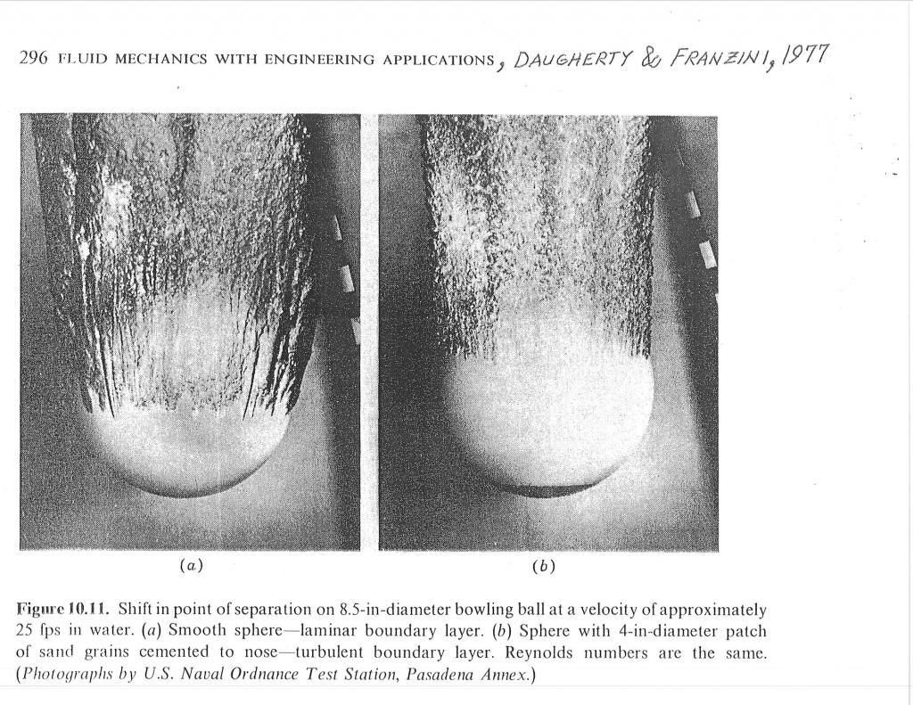
*Any analog watch or clock face could be used to pattern a successful 'template.' Compare this to the 2014 VW XL1.
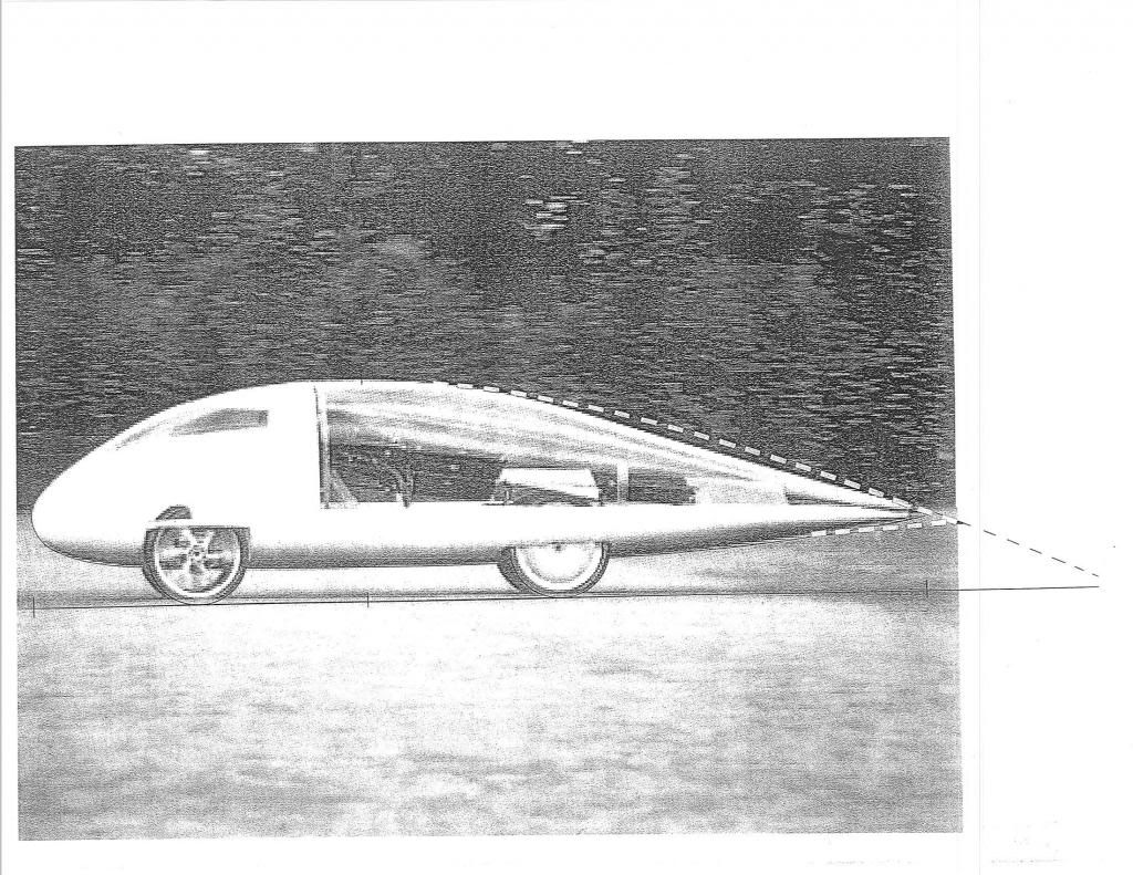
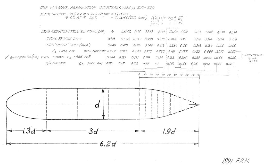
*Here is Mair's 1969 'Template' for a 'best' boat tail.He never goes beyond 22-degrees,and he takes awhile to get there.If you remove the constant-velocity portion of Mair's 'Gavre artillery projectile',simply combining the nose and tail,you get a pretty fine 'Template.' It's already in mirror-image ground reflection.Just cut away for ground clearance and add wheels.
*Estimating Mair's 'Template' as a simple car model,we'd have Cd 0.448 with no boat-tailing,Cd 0.284 at Mair's recommended truncation (the hashed vertical line),and Cd 0.166 with full tail.
Here is a drag breakdown provided by HOT ROD Magazine in 1962.The 'Form' drag component is what streamlining is about

Here is a aero power relationship table from Walter Korff in 1963,denoting the cube function of aero power requirements as a function of velocity,for a car of 25-sq-ft frontal area
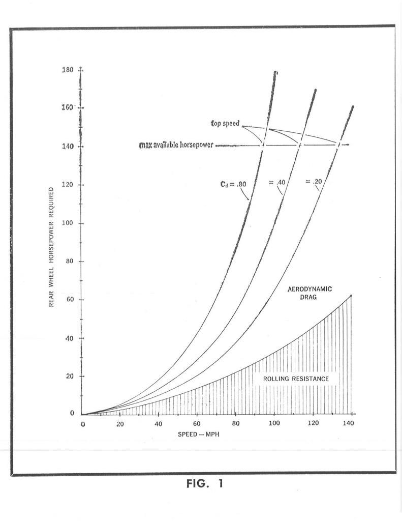
Here is a HOT ROD table depicting the relationship of Cd,velocity,as it pertains to aero hp load.

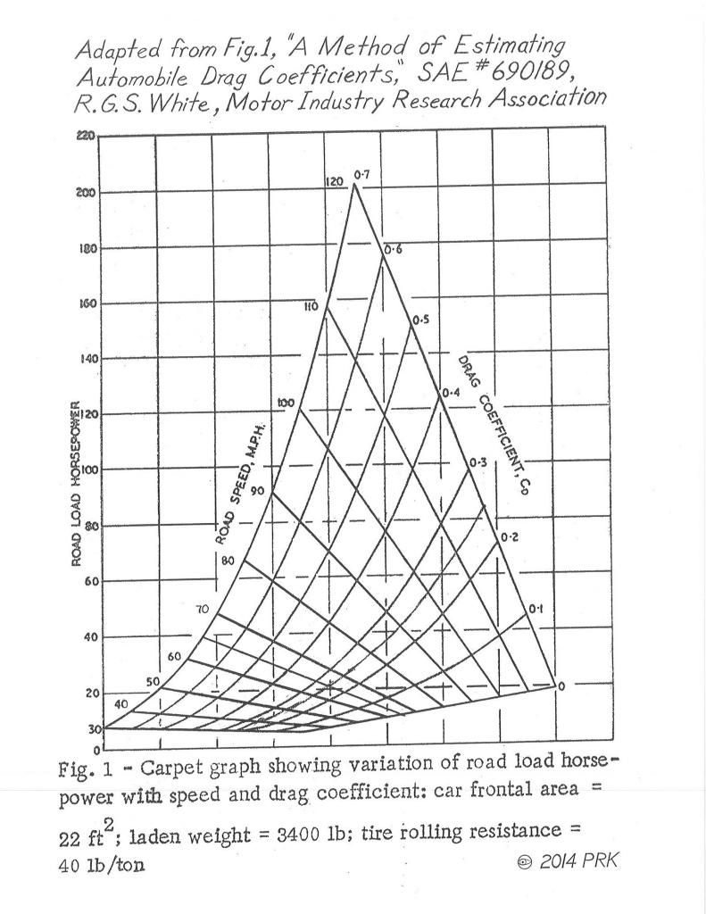
Here is R.G.S.White's drag table for a vehicle of 22-sq-ft frontal area
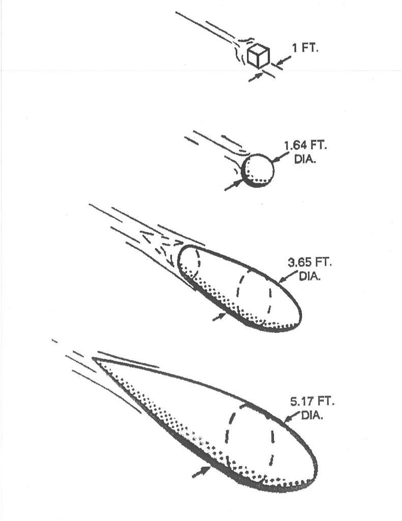
Here is a comparative chart illustrating the low-drag nature of the streamlined body of revolution.All 4 bodies have identical drag.When messengers commented in the 1970s,that we could have large vehicles with less drag than some tiny econoboxes,this is what they were referring to.
In this table,I've taken the 'golf ball' from above,and added aft-bodies of increasing radius to the forebody.In every case,flow always separates at 4-seconds seconds after 12:00 on top and 4-seconds before 6:00 on the bottom.At some radius,the separation point is lost at the longitudinal bifurcation line,leaving only the drag do to the boundary layer torus which cannot be recovered.This is the reason that streamline bodies cannot have a lower Cd than 0.04.It's all skin friction.
