Quote:
Originally Posted by TurnNBurn

Wiring is going slow because im waiting on some shrink tubing. I got all the resistors and terminal ends and im ready to wire. I'm a little hesitant because I am very new to this and I'm confused and need some help.
The contactor is what has me confused. As a kid I remember wiring 9v batteries to motors. Simple enough and im familiar with that. Ive even wired a switch between the fans and batteries. But this is new. The contactor is new ground for me.
|
Wrote up a great big reply without looking at the picture you attached (dang slow internet connection

)
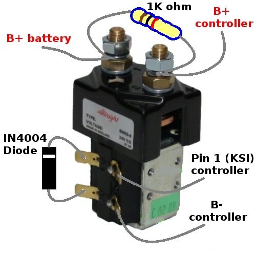
According to the wiring diagram that Ryland posted earlier in this thread.
Terminal 1 (screw terminal) goes to B+ of your battery via your battery fuse.
Terminal 3 (screw terminal) goes to B+ on the controller.
The 1000 ohm (1K ohm) 10 watt resistor goes between terminals 1 and 3. This is the precharge resistor that allows a small amount of current to go past the contactor and charge the capacitors in the controller. This avoids a large surge of current when the contactor switches.
The data sheets are a bit light on for specific details of which of the spade terminals are which.
Basically they are the coil connections with one side of the coil connected to two of the terminals and the other side of the coil connected to the other two terminals.
From one of the pictures on this site
SW200-9 | Albright single acting solenoid contactor | 72V it looks like the top two spade terminals ar the positive coil connections and the bottom two are the negative coil connections (viewed with the screw terminals being at the top).
So the bottom spade terminal goes to B- on the controller
and the top spade terminal goes to pin 1 on the controller (KSI voltage)
The IN4004 diode goes across the other two spade terminals.
Anode to the bottom spade terminal
and cathode to the top spade terminal.
On the diode the cathode end is the end that has the white ring painted around it.
I will have a go at editing your picture to make it clearer.
Please be aware i have never used this brand of contactor and so all this is based on what images/data i could locate on the internet. Might be best to wait till a few others chime in to say if it is correct or not.