Yea! Some progress with the resolver driver!

It's working! Just a couple of problems - an incorrect resistor and a cold solder joint. Fixed those, and the board works great!
Here's a pic of the test:
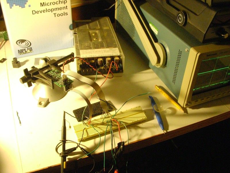
The flat ribbon cables are the input/output from the circuit, the red/black cable provides 24V to power the driver amplifier. The larger ribbon cable on the right is for all the sensor I/O of the MGR. Right now the test cable is connected to the MGR rotor sitting on my desk. It includes the resolver carrier signal, the sin and cos return signals, and a temperature probe. The smaller one is just for testing; it includes all the output signals and 5V board power. This one plugs directly into the QEI interface terminal on Paul's board.
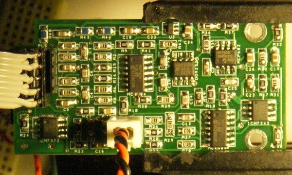
Here's a close-up of the board itself. I've got to say, it would have been a LOT easier to debug on a through-hole circuit board. One big thing I'm going to change on my next board is to add some test-loops for places to attach the 'scope probes.
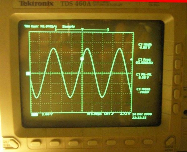
Here's a fuzzy shot of the output from my "new" scope. This is the carrier signal, running at 62.5kHz, with a p-p voltage of 9.6V.
I need to get my old computer running with the PC scope, then I'll post some pics of the output signals.
- E*clipse