Quote:
Originally Posted by MPaulHolmes

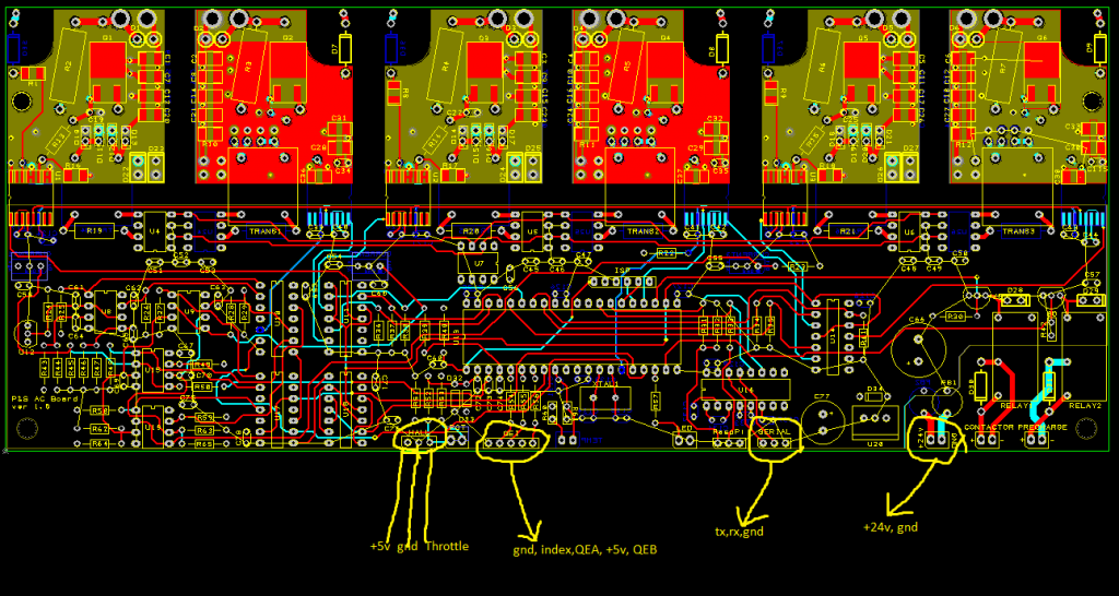
Holy mackeroni, I forgot about the encoder ticks. That needs to be programmable! I'll include that next with the rotor time constant addition. Then I'll send you a big fat .hex file and .c and .h files that have it all. Here's a pinout for the control board. (You don't need the index pin for the encoder. the microcontroller will just ignore it in the case of an ac induction motor):
 |
Ran into a bit of a problem .. or it could be a problem .. my hohner encoder is 9V - 24V, not 5V. I'll look at my other encoder, but it is the same brand and a similar vintage.
I guess I will start without the encoder and 'see what happens'.
Powering the encoder with the raw 24V from the DC/DC is a possibility, then using optoisolators to drop the voltage down to 5V would work but it's going to take me some time.
If the 5V ground and the 24V ground are common, I could use a resistor divider to drop the signals down to 5V. The optoisolators can take a clean square wave and add some slope to the signals. I know I could look at the schematic, but I'd likely end up verifying with you anyway!