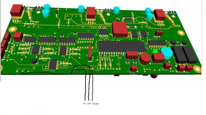
Would the following modification work for using a hall effect throttle controller? It is hard to see in the picture but the idea is to cut the trace where the red X is (looks like a red blob on this picture) and then swap +5 and Gnd as compared to Paul's original picture. Doing this would make my pinouts a little cleaner.
Looking at the schematic it looks like if the resister R46 was removed then the 2 pads for +5 and gnd would not be connected to anything so their polarity wouldn't matter.
