Fan Control Basics:
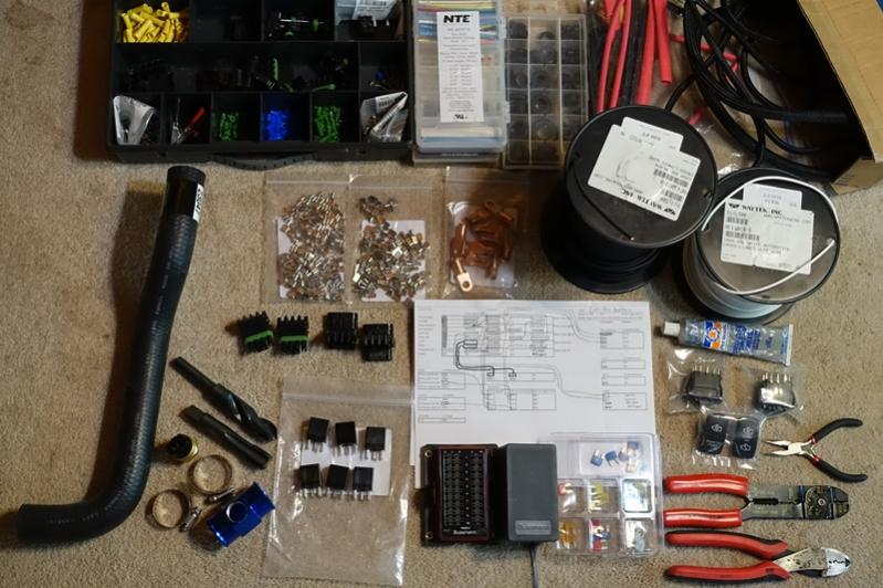
Looking at controllers, I found typically the reliability to be sub-par and many used a temperature sensor stuck in the radiator fins which I am not a big fan of. I decided to assemble a basic two speed controller myself. For the base of the fan controller, I decided to use a Cooper Bussmann RTMR 15303-4-0-4 panel. I have used these for prior automotive wiring projects and already had a selection of pins and plugs to go in them. I chose a non-bussed model because a buss would interfere with some of the logic. Also the non-bussed panels are easier to waterproof. I made an aluminum RTMR under hood mount for my Tacoma, these are for sale online but simple enough to make. I used 5 pin Song Chuan ISO 280 micro relays, because the logic requires access to both the on and off positions of the relay. I also used a selection of wire, fuses, weatherpack connectors, heat shrink, protective wire loom, spade terminals, and a variety of other small electrical components.

As previously stated, the Camry fan does not have low/high functionality because in the Camry it actually has a voltage controller to control the speed. I got a free Camry controller when I bought the Camry fans (used out of a junkyard) and after opening it, quickly discovered it was of absolutely no use without a micro-controller, which is beyond the scope of this swap. I wanted to have two speed settings, but I wasn't too keen on using resistors to slow down the fan, since that method wastes energy heating the resistor. I decided the best way to slow the fans but maintain full efficiency would be to have the two fans wired in series for the low speed, and then take them out of being in series and put them in parallel for the high speed. I will explain how that is accomplished in the logic section below. Having the fans in series would divide the voltage each fan saw in half, while being in parallel would allow full voltage at both fans. Testing the fans with a current meter and a battery, the fans in series pulled roughly 3 amps for the pair and in parallel they pulled about 5 amps each so about 10 amps total.
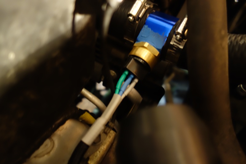
The controller needs to know what the engine temperature is. I used a Beck/Arnley 2011266 (201-1266) Radiator Fan Switch, which threads into a M22 1.5 thread. This is a two temperature switch, kicks on low about 195 F and high about 205 F, and kicks off a few degrees less than the kick on temperatures. This is a ground triggering switch, so it is connected to the ground side of the control relays. The key part of this temperature switch is insulated ¼” female spade terminals fit the prongs exactly, so no searching for rare factory connectors. I was unable to locate a M22 1.5 hose adapter (very rare), so I purchased an inexpensive 36mm 1.42" 1/8 NPT Water Temp Gauge Radiator Hose Sensor Adaptor, a 13/16 Drill Bit, and a M22 1.5 Tap. I drilled out and tapped the hose adapter, installed the temperature switch, cut a section out of a spare Tacoma upper radiator hose, installed the hose adapter, partially drained the coolant from the radiator, installed the new hose, and replaced the coolant following the procedure in the manual. I had this made early on, but put this in the truck at the same time I installed the new fan shroud, one of the last steps in the swap.

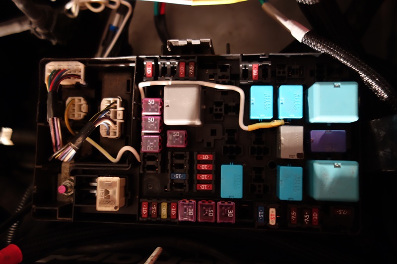
The fan controller also needs to know when the AC compressor is on, and should be running at least on low when the compressor is compressing. I did this by tying into the output of the relay that runs the magnetic clutch using a modified fuse tap. Note this is a high power positive circuit being tapped and cannot directly be used to control the fan relays which are ground triggered, so I ran this through a fuse and then used this as a positive trigger (pin 85) of a fourth relay. When the compressor kicks on, the fourth relay now turns on, which connects the fan low relay trigger to ground pins 30 using and 87 of the relay. This will make the fan low circuit kick on, exactly like if the temperature switch kicked on low.
