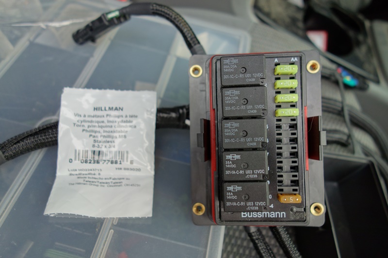
Control Logic and Wiring:
I will post my schematic, but it is important to understand how the circuit works if you actually want to construct it. In order to be able to switch the fans in and out of parallel and series, three relays are required, two five pin and one four pin. The five pin relays have an output pin for both when the relay control circuit is off and when it is on. The four pin relays only have a pin for when the control circuit is on.
In a nutshell, you take the first fan and connect it's positive lead to the battery through a fuse. You take the second fan and connect its negative lead to a ground. Then you connect the other two leads of the fans to the switched input leads (pin 30) of the two five pin relays (not the control leads, not the output leads). The on output leads (pin 87) of the relays are connected where the first fan's relay connects it to ground when it is on, and the second fan's relay connects it to 12v through a fuse. Thus when these relays are turned on, both fans see a full voltage circuit as they are in parallel. Current flows in this order, battery positive terminal, fuse, Fan 1 + to -, fan 1 relay input through on output, and then to ground. Independently, current also battery positive terminal, fuse, fan 2 relay on output to input, Fan 2 + to -, and then to ground.
Now when both relays are turned off, neither fan is on, because the first has no ground and the second has no 12v power. However, through the use of the 5 pin relays, both of these relays connect their input pin to the off output pin (pin 87A). If you connect the input and on output pins (30 and 87) of the third relay to the two off output pins (pin 87A) of the first two relays, then when the third relay is turned on, it connects the circuit through both fans, where each fan sees half the voltage as they are in series. Following typical + to convention (not the electrons), current flows in this order, battery positive terminal, fuse, Fan 1 + to -, fan 1 relay input through off output, third relay through the input to the on output, fan 2 relay off output to input, Fan 2 + to -, and then to ground. Thus the fans can be switched from series to parallel. Trigger the third relay to turn them on low, and trigger the first two relays to turn them on high. Note the fans will turn on high regardless of the position of the third relay.
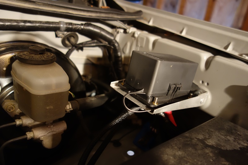
Since the RTMR is a five relay panel, and I only used four relays thus far, I hooked up an extra relay controlled fused accessory circuit. I also hooked up an extra always on fused accessory circuit.
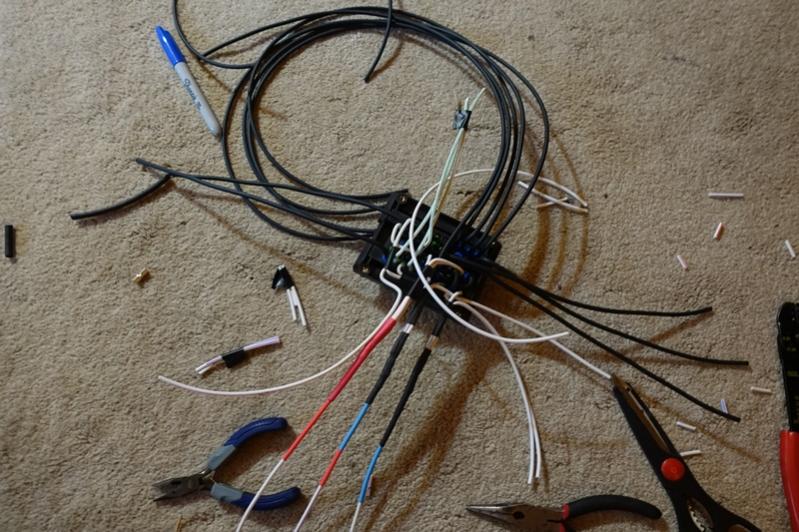
The only thing left is to just wire it all up! I attached two color coded excel files, these show how the wires go into the RTMR, too all the accessories, and how to hook up the switches in the cab.