What I had in mind wasn't as flexible as you guys were thinking. I was first trying to come up with something that could be well matched to the massive number of 10HP motors out there. A guy in india was wanting a totally through-hole controller so they could easily assemble it for their rickshaws. They also only were able to do 72vDC for their 400vAC motors. No boosting would not be good in that situation I think. Here's the power board:
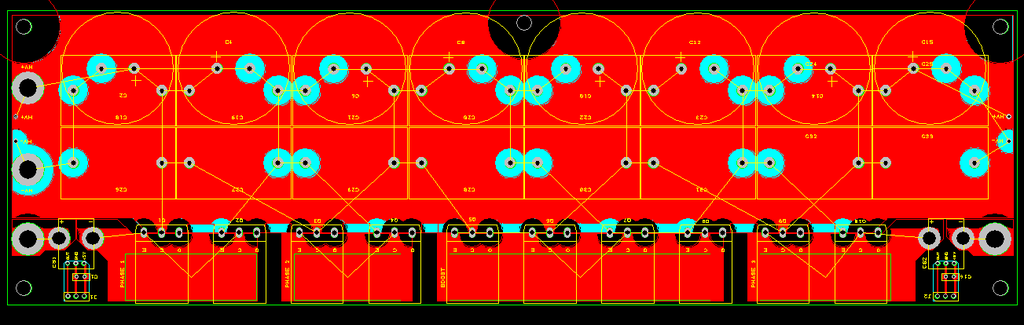
Notice that the power board is designed for 3 separate phases, with 2 IGBTs (to form a half bridge) per phase, plus 4 IGBTs for the boosting section. That way you could boost, say, 150 amps (shared between 2 IGBTs) at 150v up to 75amps at 300volts. Then the 300volt section would be happy with 1 IGBT, and the low voltage section would be happy with the 150amps shared between 2 IGBTs. Then, to minimize the stray inductance, the driver board mounts perpendicularly to the power board, and the IGBT legs get soldered directly to the driver board. So, the driver board is designed to fit exactly with the footprints of the to-247 IGBTs. The IGBTs get clamped against the base plate with the mounting hardware accessible, "south" of the power board. The legs get bent at a 90 degree angle, and go through the power board, stick through and get soldered to the driver board. It should work OK with 247C and 247D length legs.
Also, notice that the power board accepts either 16 film caps or 8 film caps and 8 electrolytic caps. Exclusive use of film caps would allow for switching at maybe 700v.
Also, notice that 2 of the current sensors are on the power board. There's a new type of current sensor that goes up to 100amp, and is only $8 each, and has a response time of like 1uS. So, 2 of the phases are monitored cheaply (and that's all you need). An external sensor would be needed for the boost section for hardware overcurrent protection. To keep things small, you have to solder the 6 gauge or whatever cable to the surface of phase 2, and to the boost section.
Doing it this way makes the size about 12.35" x 3.6" x 3.6" or so, so it's pretty small and not much wasted space. The down side is it's very much not flexible, but there is no wiring and twisting wires to the power section. The nice thing is, it's really cheap, about as cheap as I can make it.
I could have the 2 microcontrollers speak if I doubled up on the PGC and PGD, which means adding a switch after it is programmed. But then that means possibly changing the pins of the debugger (you have 3 choices for the 2 debugging pins). I could then do the throttle & brake & temperature & temperature2, & voltage on the dspic2010, but would have to send the data to the other one. That means adding voltage monitoring, which adds around $15 or so cost, which isn't bad. There's room on the control board.
The control board is going to be cheap to make, so I could make the other changes later too. I was just trying to do "good enough" for as cheap as possible, without too much extra complexity. I guess I started worrying about messing with PGC and PGD and debugging and sending the important things like throttle so that the dspic4011 then had 2 separate UART conversations going at the same time (uart1 and uart2).